Grid forming is not an option bolted onto an inverter; it is the work of defining a new type of generator that the grid can rely on.
To state the conclusion first: through deliberation by the Electricity Regulatory Commission on April 10, 2026, the Korea Power Exchange amended the Power Market Operation Rules, mandating that BESS (battery energy storage systems) in the second central contract market (540MW) completed by the end of next year (2027) be equipped with PCS (power conversion systems) that have grid-forming (GFM) capability. It plans to keep extending GFM to BESS entering commercial operation in 2028 and 2029 (540MW and 600MW, respectively). BESS operators participating in Korea’s central contract market must reflect GFM performance criteria in their PCS procurement specifications starting with volumes completed in 2027.
The cost of adopting GFM is about KRW 20 million per MW, roughly one tenth of a synchronous condenser at KRW 200 million per MVar, and this is the economic rationale for the mandate.
E2News reported this on April 9, 2026, citing presentations at the “Power Electronics Technology Forum Toward RE 100GW” hosted by the Korean Institute of Power Electronics. As inverter-based resources (IBR) connecting to the grid increase, there is concern about grid weakening as system inertia declines; GFM operates as an independent voltage source that forms its own voltage and frequency, providing inertia and fault current to the grid and maintaining synchronization through disturbances.
Overseas grid operators and bodies, including NERC, MISO, and ERCOT in North America and ACER and ENTSO-E in Europe, are also moving toward mandating GFM capability for IBR. In Korea, the Korea Power Exchange demonstrated a 500kW-class GFM inverter for the first time on Jeju in 2024, and Korea Grid Forming put a 110kVA-class GFM BESS into commercial operation in the Gwangyang Bay microgrid last year. In Australia, AGL Energy’s 250MW Torrens Island BESS in South Australia and the 50MW Broken Hill BESS in New South Wales were presented as demonstration cases.
Precondition: the exact control parameters of GFM inverters (virtual inertia constant, real-time SCR estimation algorithm, and so on) differ by manufacturer and model and have not been disclosed, so the checklist below is developed on the basis of a typical BESS PCS configuration centered on the GFM performance requirements published by the Korea Power Exchange (fault current, synchronization, self-start). In actual application, it must be replaced and verified against the original text of the Power Market Operation Rules amendment and KEPCO’s grid interconnection standards.
Safety interlock check order (top priority)
- Voltage source hold interlock — a GFM PCS must operate as a voltage source even during a grid fault and must sustain an instantaneous fault current of 2.0 p.u. or more for at least 140ms.
- Seamless GFL-GFM mode transfer interlock — based on real-time estimation of SCR (short-circuit ratio), it switches seamlessly between grid-following (GFL) and grid-forming (GFM) modes, and no loss of synchronism may occur during the transfer.
- Virtual inertia constant upper-limit interlock — excessive virtual inertia can actually cause severe active power fluctuations (the Broken Hill BESS case in Australia), so the virtual inertia constant is limited to no more than the value fixed by grid impact assessment.
- Self-start (black start) interlock — the system must be able to start itself without an external power source even when the grid is in a complete blackout.
- Preventing conflict with the fault current limiting function — the voltage-source behavior and the fault current limiting function for overcurrent protection can conflict, so protection coordination on the grid side and the equipment side is reviewed together; in no case does this site cover designs that replace or bypass the hardware protective relay and breaker linkage with software logic alone.
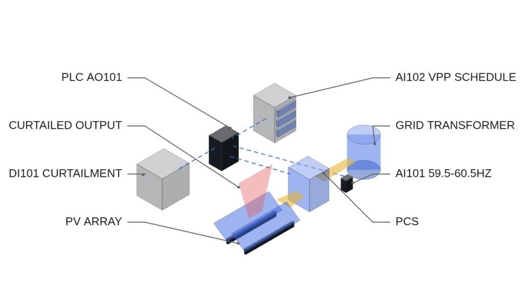
GFM BESS PCS I/O map
| Signal | I/O address | Type | Operating condition |
|---|---|---|---|
| Grid SCR estimate | AI401 | Analog In | Real-time short-circuit ratio estimate; GFM mode transfer decided when at or below threshold |
| GFM/GFL mode status | DI401 | Digital In | 1 = GFM mode, 0 = GFL mode |
| Fault current command | AO401 | Analog Out | Instantaneous fault current 2.0 p.u. or more, held for at least 140ms |
| Virtual inertia constant setting | AO402 | Analog Out | Limited to no more than the upper limit fixed by grid impact assessment |
| Black start command | DO401 | Digital Out | Starts the self-start sequence on detecting a complete grid blackout |
| Local protective relay trip | DO402 | Digital Out | Trips immediately on overcurrent or overvoltage detection regardless of GFM mode (top priority) |
The implication of this I/O map is clear. If AO402 (virtual inertia constant) is raised arbitrarily without grid impact assessment, it can instead cause voltage dips and rises and repeated FRT (Frequency Ride-through) operation, as in the Broken Hill BESS case in Australia. Korean BESS operators must apply the grid impact assessment result, reflecting the PCS manufacturer’s model, directly as the upper limit of AO402.
PLC logic snippet (IEC 61131-3 Structured Text pseudocode)
(* GFM BESS PCS mode transfer logic - local protection first, virtual inertia upper limit *)
(* AI401: SCR estimate, DI401: GFM/GFL mode status, AO402: virtual inertia constant *)
IF (OVERCURRENT_DETECTED OR OVERVOLTAGE_DETECTED) THEN
    DO402 := 1; (* Local protective relay trips immediately, regardless of mode *)
ELSIF AI401 <= SCR_THRESHOLD THEN
    DI401 := 1; (* Enter GFM mode, seamless transfer *)
    AO402 := MIN(AO402_SETPOINT, GRID_IMPACT_ASSESSMENT_LIMIT); (* Virtual inertia upper limit *)
ELSE
    DI401 := 0; (* Remain in GFL mode *)
END_IF;
(* DO402 is kept on an independent hardware path, independent of GFM/GFL mode status *)
Boundary conditions — handling field variables
The interaction characteristics of multiple inverters when GFM inverters are connected to the actual grid at scale, and the direction for re-establishing protection coordination, will be settled by additional research and large-scale demonstration results that the Korea Power Exchange and KEPCO will carry out through 2028, so they require waveform analysis and field measurement. In addition, the largest GFM inverter test facility in Korea is currently 2MW, so a verification procedure for products from manufacturers building 2.5MW-and-larger equipment has not yet been clearly established. The selection criterion condenses to one question: when reviewing the PCS procurement specification, is there a separately implemented upper-limit logic that restricts the virtual inertia constant to the grid impact assessment value?
References
E2News, “Grid-forming inverters mandatory for BESS entering commercial operation from next year” (2026-04-09)
WO2024150838A1 — Gwangju Institute of Science and Technology (GIST), Inverter using grid forming and method of operating the inverter (Google Patents; WO-stage status Ceased; the Korean national-phase application KR1020257022075A appears to be in progress, but whether it has been registered requires separate verification)