The short answer first. An emergency diesel generator (EDG) load sequencer takes on a different character depending on whether the step interval is a fixed timer or a voltage-and-frequency recovery check. Recovery-based sequencing loads faster by following the actual generator response, but if recovery is never confirmed, the next step waits indefinitely. The practical answer is therefore not one or the other but “recovery check first, forced advance on a ceiling timer,” and the key design judgment is whether that ceiling fits inside the loading timeline assumed by the safety analysis.
Start with the safety interlock conditions
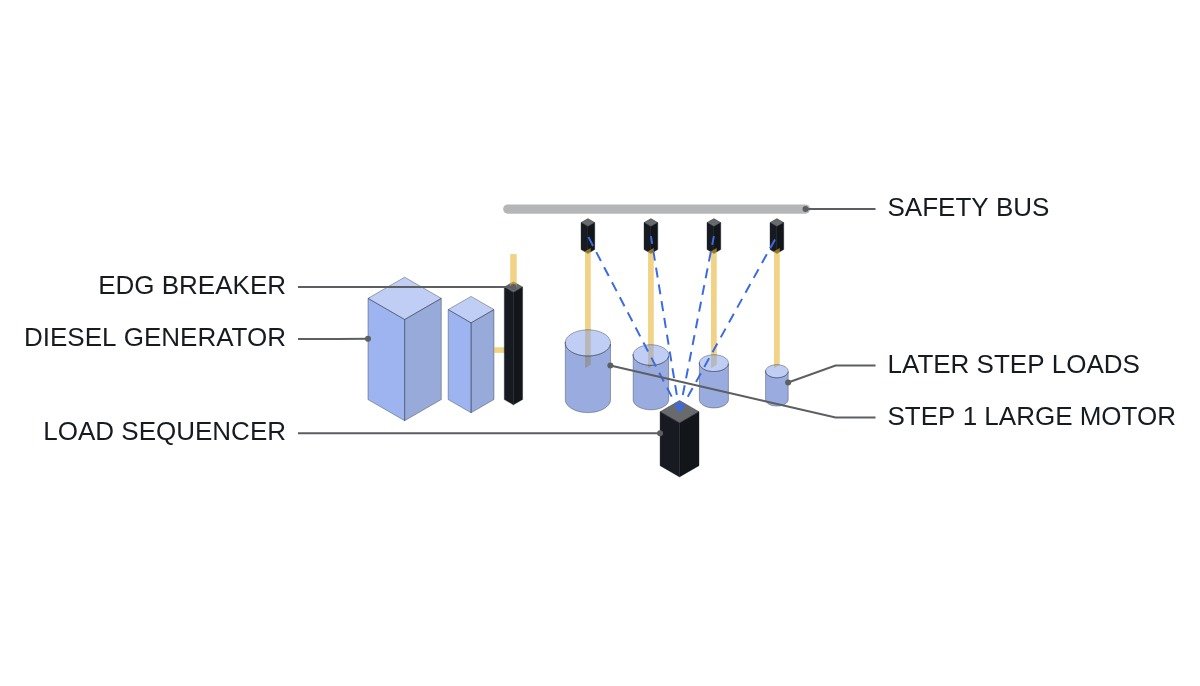
From the moment the EDG connects to the safety bus, that one generator is the bus’s only source. The interlocks have to look two ways at once: interlocks that protect the generator, and interlocks that are released in an emergency to protect the safety function. As a general design principle, the generator and engine protections retained in emergency start mode are kept to a small set, and the exact list must be confirmed against the plant’s licensing documents.
- □ Confirm the EDG breaker close permissive includes both “safety bus dead” and “offsite supply breaker open.” This removes any path to asynchronous paralleling of offsite power and the EDG.
- □ Confirm bus load shedding is complete before sequencing starts. If the EDG closes onto a bus with load still connected, the first step is larger than designed.
- □ Confirm the list of protections retained in emergency start mode (for example, engine overspeed and generator differential) and those bypassed matches the wiring diagrams.
- □ Confirm bypassed protections still annunciate in the control room. Block the action, not the information.
- □ Define sequencer failure behavior. If the sequencer stops, loads already connected stay on and the remaining steps can be loaded manually.
Fixing the conditions on a timing chart
A load sequence depends on its premises, so this article develops the logic on the timing chart below. Specific times depend on each plant’s safety analysis, so they are kept as symbols.
- T0: safety bus undervoltage detected, start signal issued, bus load shed command issued.
- T0 to T1: EDG starts. Rated voltage and frequency confirmed (T1). This time must be within the limit set in the licensing basis.
- T1: after dead-bus confirmation, the EDG breaker closes.
- T1 to T2: step 1 loads. Put the largest motor loads in the early steps; the generator recovers from inrush-induced voltage dip more easily when it is close to no load.
- Step n: loads on whichever comes first after the previous step, voltage/frequency recovery or ceiling timer expiry.
- After the final step: sequence complete signal, manual loading permitted.
Step order follows two rules. Loads needed first for the safety function go first, and within the same priority, loads with larger inrush go first. When the two rules conflict, the load timing assumed in the safety analysis wins, and the voltage dip problem is solved by splitting steps.
Load sequencer pseudocode (IEC 61131-3 ST)
(* I/O MAP - train A load sequencer *)
(* %I3.0 : DI_EDG_READY_VF      - EDG at rated voltage and frequency *)
(* %I3.1 : DI_BUS_DEAD          - safety bus dead confirmed *)
(* %I3.2 : DI_OFFSITE_BRK_OPEN  - offsite supply breaker open *)
(* %I3.3 : DI_LOAD_SHED_DONE    - load shedding complete *)
(* %IW10 : AI_BUS_VOLT_PCT      - bus voltage, % of rated *)
(* %IW11 : AI_BUS_FREQ_PCT      - bus frequency, % of rated *)
(* %Q2.0 : DO_EDG_BRK_CLOSE *)
(* %Q2.1 : DO_STEP_1 ... %Q2.4 : DO_STEP_4  - load permit per step *)
(* %Q2.7 : DO_SEQ_COMPLETE *)

(* 1. EDG breaker close interlock - blocks asynchronous paralleling at the source *)
DO_EDG_BRK_CLOSE := DI_EDG_READY_VF AND DI_BUS_DEAD
                    AND DI_OFFSITE_BRK_OPEN AND DI_LOAD_SHED_DONE;

(* 2. Recovery check - TRUE when voltage and frequency are inside the recovery band *)
X_RECOVERED := (AI_BUS_VOLT_PCT >= R_V_RECOVER) AND (AI_BUS_FREQ_PCT >= R_F_RECOVER);

(* 3. Step advance - recovery first, forced on ceiling timer (T_STEP_MAX) expiry *)
TON_STEP(IN := DO_EDG_BRK_CLOSE AND (N_STEP < 4), PT := T_STEP_MAX);
TON_MIN (IN := DO_EDG_BRK_CLOSE AND (N_STEP < 4), PT := T_STEP_MIN);   (* minimum interval *)

IF TON_MIN.Q AND (X_RECOVERED OR TON_STEP.Q) THEN
    N_STEP := N_STEP + 1;
    IF TON_STEP.Q AND NOT X_RECOVERED THEN
        X_FORCED_STEP_ALM := TRUE;     (* forced-advance record - control room alarm *)
    END_IF;
    TON_STEP(IN := FALSE); TON_MIN(IN := FALSE);   (* restart timers *)
END_IF;

DO_STEP_1 := N_STEP >= 1;
DO_STEP_2 := N_STEP >= 2;
DO_STEP_3 := N_STEP >= 3;
DO_STEP_4 := N_STEP >= 4;
DO_SEQ_COMPLETE := N_STEP >= 4;
(* R_V_RECOVER, R_F_RECOVER, T_STEP_MIN, T_STEP_MAX are symbols; actual values depend on the safety analysis *)
T_STEP_MIN exists for the case where recovery is confirmed too early. If the voltage regulator passes through the recovery band momentarily during its transient response, the next step lands and transients stack. The minimum interval is the floor that prevents that stacking; the ceiling timer is the cap that prevents an endless wait.
Comparison of step-advance methods
| Method | Loading speed | If check fails | Analysis fit |
|---|---|---|---|
| Fixed timer | Constant | Advances regardless | High |
| Recovery only | Fast | Waits indefinitely | Low |
| Recovery + ceiling | Fast, capped | Advances at ceiling | Secured by ceiling |
| Recovery + floor + ceiling | Fast, no stacking | Advances at ceiling | Secured by ceiling |
The column that decides this is analysis fit. The safety analysis assumes “load X is connected within so many seconds,” so any method that could load later than that assumption is unusable. To use recovery-based sequencing, the ceiling timer must be shorter than the analysis assumption, and at that point its advantage becomes margin: on average, it loads earlier than required.
What to confirm in field testing
In a sequencer test, record per step the voltage minimum and recovery time, and the frequency minimum and recovery time. If the voltage dip on a large-motor step is deeper than expected, the cause is generator excitation response, motor starting characteristics, or cable impedance, but which one requires waveform analysis and field measurement. A slow recorder sampling rate will miss the minimum, so record the transient window separately at a sufficiently high sampling rate.
The other item is contention between load shedding and sequencing signals. If the shed signal is maintained, it can coincide with the sequencer permit and keep loads from connecting. Load shedding must clear right after the EDG breaker closes and hand control to the sequencer.
Boundary conditions
The advantage of recovery-based sequencing reverses when EDG capacity margin is small. In a design where the generator is loaded close to its rating, the last steps recover slowly and most steps end up advancing on the ceiling timer. In that case, recovery logic only adds complexity and behaves essentially like a fixed timer. Conversely, with ample capacity margin, recovery checking creates substantial margin against the analysis assumption.
The single decision rule: if testing shows most steps confirm recovery before the ceiling timer, use recovery with floor and ceiling; if not, use a fixed timer.