Conclusion. LG Energy Solution announced on September 7, 2026 that, in joint research with the team of Professor Lim Jong-woo of the Department of Chemistry at Seoul National University, it had published in Nature Communications a result that improves the prospects of applying LMR (lithium manganese rich) batteries to large-format cells. There are three key figures. Lowering the upper charge voltage from 4.6V to 4.3V raised the reduction rate of oxidized oxygen from 86% to 97%; carrying discharge down to 2.0V instead of 3.0V restored the oxygen almost to its original state; and a 40Ah-class large-format cell operated under these conditions retained 92.2% of its initial energy after 883 charge-discharge cycles.
From an electrical engineer’s point of view, this announcement is not materials news but BMS (Battery Management System) setpoint news. The life interlock of an LMR cell hangs on two parameters: the upper and lower limits of the cell voltage window. The conclusion is “an asymmetric voltage window that lowers the upper limit and opens the lower limit even further,” and transplanting the BMS lower limit that has become standard for NCM (typically in the 2.5–3.0V band) as-is actually works against it.
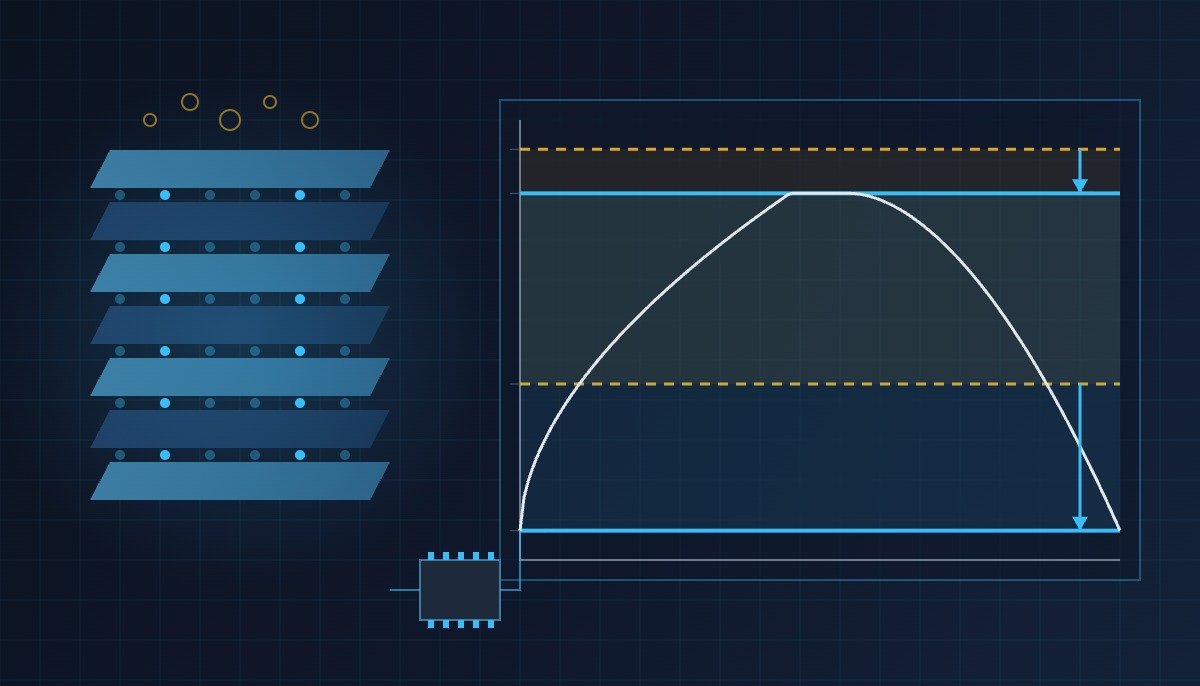
In BMS design we learn that the discharge lower limit is a “protection item,” not a “performance item.” In LMR, the lower limit governs performance (the oxygen recovery rate). This is a cell where a low lower limit is not something reluctantly “allowed” but something to be set as a “design condition” from the start.
Some background. LMR is a next-generation cathode material that uses no cobalt and is based mainly on inexpensive manganese; it achieves high energy density by using not only transition metals such as nickel and manganese but also the oxygen inside the material for energy storage. The problem is that if the oxygen oxidized during charging is not fully recovered during discharge, it causes internal structural damage and gas generation. In large-format EV cells, where internal free space is limited, this gas leads directly to internal pressure rise and performance degradation, and it has been regarded as the biggest obstacle to commercialization.
This joint research showed that the variables governing oxygen recovery lie not only in the upper charge limit but also in the lower discharge limit, and on that basis redesigned the operating voltage range and the activation (formation) process conditions for the 40Ah-class cell. In particular, a process that lowers the temperature during the activation step suppressed the gas generation characteristic of large-format cells.
There is one observation from the field that runs against intuition. Lowering the upper limit from 4.6V to 4.3V means giving up usable capacity, which designers instinctively avoid, and lowering the lower limit from 3.0V to 2.0V is avoided even more from the standpoint of over-discharge protection. Yet this cell only reaches a life of 92.2% after 883 cycles when both directions are moved at the same time, “more conservative (upper limit)” and “less conservative (lower limit).” In other words, resetting a single BMS parameter to match the cell chemistry carries the same weight as a materials improvement. In Professor Lim’s words, “the stability of a cell can be improved through electrochemical protocol design alone,” and from the electrical side, the entity that executes that protocol is the BMS.
Preconditions (based on the operating time chart). The published figures are five: upper charge limit (4.6V→4.3V), lower discharge limit (3.0V→2.0V), cell capacity (40Ah class), cycle result (883 cycles, 92.2%), and the use of low temperature in the activation process. The test C-rate, test temperature, cell-to-cell variation conditions, the voltage window to be applied to production cells, and the balancing method at pack level are not in the announcement. The I/O map and logic in this article carry only those five figures over as “setpoints,” and the time and temperature conditions are left as items to verify.
Activation (formation, low-temperature process) → cycle charge (CC/CV, switch to CV on reaching the 4.3V upper limit, then terminate) → rest → discharge (terminate on reaching the 2.0V lower limit) → rest → repeat (883 cycles as reference). Current and temperature values for each segment are not disclosed.
Safety interlock check sequence (top priority)
- Confirm the hardware protection path is independent — protection-grade hardware such as the overcharge protection (OVP) circuit, contactor opening and fuses must operate independently of the BMS software voltage window parameters. Changing the voltage window to 2.0–4.3V is a software parameter change, and this article does not cover any description of bypassing or relaxing hardware protection settings in software.
- Separate the protection-grade upper limit from the operating-grade upper limit — the operating (diagnostic) grade upper charge limit of 4.3V and the protection-grade hard-cut upper limit above it are managed as separate setpoints on separate output contacts. The actual value of the protection-grade upper limit must be confirmed with the cell manufacturer’s specification.
- Cell variation interlock before applying the 2.0V lower limit — when the lower limit is lowered to 2.0V in a pack, cells with large variation can go even lower. Set the minimum cell voltage and the cell-to-cell deviation (ΔV) as separate conditions, and automatically revert the discharge lower limit to a conservative value if the deviation condition is not met.
- Keep the EMO (emergency off) hardware path — under any voltage window setting, the EMO circuit must open the contactor without passing through the BMS logic.
LMR cell voltage window management I/O map (example)
| Signal | I/O address | Type | Operating condition |
|---|---|---|---|
| Cell voltage (max) | AI_CELL_V_MAX | Analog In (V) | At ≥ 4.30V, switch to CV, terminate charge |
| Cell voltage (min) | AI_CELL_V_MIN | Analog In (V) | At ≤ 2.00V, terminate discharge |
| Cell-to-cell deviation | AI_CELL_DV | Analog In (mV) | If deviation limit exceeded, revert discharge lower limit to conservative value |
| Pack current | AI_PACK_I | Analog In (A) | Judges termination current in the CV segment |
| Cell temperature | AI_CELL_T | Analog In (°C) | Temperature conditions not disclosed — to be verified |
| Charge enable | DO_CHG_ENABLE | Digital Out | Operating grade — ON when below 4.30V and deviation normal |
| Discharge enable | DO_DCHG_ENABLE | Digital Out | Operating grade — ON when above 2.00V and deviation normal |
| Hardware OVP status | DI_HW_OVP | Digital In | Protection grade — opens contactor regardless of software |
| Contactor open | DO_CONTACTOR_OPEN | Digital Out | Protection grade only, hardwired in parallel with EMO |
The implication of this I/O map fits in one line. What produced 92.2% after 883 cycles is the thresholds on two analog inputs, AI_CELL_V_MAX and AI_CELL_V_MIN, not new hardware, and those thresholds act only on DO_CHG_ENABLE and DO_DCHG_ENABLE (operating grade), leaving DI_HW_OVP and DO_CONTACTOR_OPEN (protection grade) untouched.
PLC logic snippet (IEC 61131-3 Structured Text pseudocode)
(* LMR cell voltage window management logic - operating grade only, fully separated from protection grade (DI_HW_OVP) *)
(* Note: this is not actual BMS firmware of any product but a conceptual example that carries the published figures (4.3V/2.0V) over as setpoints *)

VAR CONSTANT
    V_CHG_MAX_LMR   : REAL := 4.30;   (* Upper charge limit, published figure: 4.6V -> 4.3V *)
    V_DCHG_MIN_LMR  : REAL := 2.00;   (* Lower discharge limit, published figure: 3.0V -> 2.0V *)
    V_DCHG_MIN_SAFE : REAL := 3.00;   (* Conservative lower limit to revert to on abnormal deviation *)
    DV_LIMIT_MV     : REAL := 50.0;   (* Cell-to-cell deviation limit - example value, finalize after measurement *)
END_VAR

VAR
    AI_CELL_V_MAX, AI_CELL_V_MIN, AI_CELL_DV, AI_PACK_I : REAL;
    DI_HW_OVP  : BOOL;   (* Hardware overcharge protection status, cannot be changed by software *)
    DO_CHG_ENABLE, DO_DCHG_ENABLE : BOOL;
    V_DCHG_MIN_ACT : REAL;
END_VAR

(* Deviation interlock: apply the 2.0V lower limit only when deviation is normal, otherwise revert to conservative limit *)
IF AI_CELL_DV <= DV_LIMIT_MV THEN
    V_DCHG_MIN_ACT := V_DCHG_MIN_LMR;
ELSE
    V_DCHG_MIN_ACT := V_DCHG_MIN_SAFE;
END_IF;

(* Operating-grade outputs - if protection-grade DI_HW_OVP is TRUE, charging is blocked in every case *)
DO_CHG_ENABLE  := (AI_CELL_V_MAX < V_CHG_MAX_LMR) AND (AI_CELL_DV <= DV_LIMIT_MV) AND NOT DI_HW_OVP;
DO_DCHG_ENABLE := (AI_CELL_V_MIN > V_DCHG_MIN_ACT);

(* Protection grade (contactor open, EMO) is handled by hardwired circuits outside this logic - not redefined here *)
Boundary conditions — responding to field variables
The points where the advantage of this design principle flips are cell variation and temperature. If the 2.0V lower limit verified on a single 40Ah cell is applied as-is to a pack with tens to hundreds of cells in series, cells with large variation drop below the lower limit first and may be exposed to the commonly known over-discharge risks (such as current collector damage). The announcement does not state at what voltage and temperature this risk actually begins in LMR cells, so the deviation limit (DV_LIMIT_MV) and the lower limit under low-temperature conditions must be finalized after cell-level measurement and waveform analysis at the end of discharge.
Whether the 97% oxygen reduction rate holds at the 4.3V upper limit likewise depends on the CV termination current and temperature, and requires field measurement. In addition, the published result is based on cells that went through a specific (low-temperature) activation process, so it cannot be assumed that applying the same voltage window to cells made under different process conditions yields the same life. The single selection criterion is this — carry the voltage window provided by the cell manufacturer over as BMS operating-grade parameters, but design the discharge lower limit to allow 2.0V only while the cell-to-cell deviation interlock is normal, and to revert automatically to a conservative value otherwise.
References
- Electric Times (Jeongi Sinmun), “LG Energy Solution moves to commercialize next-generation LMR batteries” (2026-09-07 12:15, reporter Jeong Jae-won) — joint research with Professor Lim Jong-woo of Seoul National University, published in Nature Communications; 4.6V→4.3V oxygen reduction rate 86%→97%; discharge to 2.0V; 40Ah class, 883 cycles, 92.2%.
- Patent US12261263B2 “Lithium secondary battery” (LG Energy Solution Ltd., priority date 2022-07-20 KR1020220089894A, granted 2025-03-25, legal status Active, anticipated expiration 2042-07-21). Claim 1 claims the combination of an over-lithiated manganese-based oxide (LiaNibCocMndMeO2, 1<a, 0.5≤d<1.0) cathode active material with a silicon-based anode active material; it is explicitly noted that the upper charge / lower discharge voltage protocol in this announcement is not itself within the scope of this patent’s claims (checked directly on Google Patents).