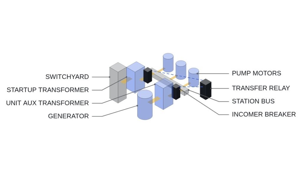
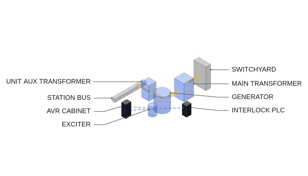
The short version: how much of a grid voltage request a nuclear generator’s excitation and AVR can accept is set first not by the capability curve but by the voltage margin on the station service bus. Where the unit auxiliary transformer hangs off the generator terminals, the more reactive power the unit absorbs (leading operation), the further both the terminal voltage and the station service bus voltage fall, eating into the undervoltage monitoring margin on the safety-related buses. So the logic that accepts reactive power requests has to put a station-bus low-voltage interlock at the same level as the over- and under-excitation limiters.
Safety interlocks come first
The excitation system is tightly coupled to generator protection, and the core task is coordinating the limiters so they act before the protective relays. If a limiter is late, a relay trips the generator, and in a nuclear unit that trip can cascade into a turbine trip and a reactor power cutback. The conditions below apply regardless of where the request comes from (main control room, dispatch center or an automatic voltage regulation scheme).
- □ Check on the P-Q plane that the underexcitation limiter (UEL) sits inside (on the safe side of) the loss-of-field relay (40) characteristic. If the curves overlap, a single leading request trips the generator.
- □ Confirm the overexcitation limiter (OEL) has an inverse-time characteristic matched to the field winding’s thermal limit and acts before field overcurrent protection.
- □ Confirm the V/Hz limiter acts before V/Hz protection (24). This matters most in the low-frequency range during startup and shutdown.
- □ Station bus low-voltage interlock. Even when a reactive-absorption request arrives, if the station bus is near its lower limit, clamp the request and report “cannot accept” upstream.
- □ AVR channel redundancy. If one channel has failed, limit the rate of change of automatic voltage requests or stop accepting them.
- □ The field breaker (41) trip and EMO circuits are hardwired; the PLC and AVR software only monitor their status.
Excitation control modes and the nuclear choice
The AVR’s base mode is voltage control, holding terminal voltage constant, and reactive power (MVAR) or power factor (PF) control is usually layered on top. A nuclear unit mostly runs baseload with little active power variation, so the mode choice comes down to grid operator requirements versus station service voltage stability.
| Mode | Controlled variable | Grid contribution | Station bus effect |
|---|---|---|---|
| Voltage control | Terminal voltage | Responds automatically to grid voltage swings | Constant terminal voltage keeps station bus stable |
| MVAR control | Reactive power output | Clear compliance with dispatch | Grid voltage swings pass straight to station bus |
| PF control | Power factor | Contribution proportional to P | With constant P, behaves like MVAR control |
| Manual (field current) | Field current | None (test or fault only) | No voltage support during grid events |
The takeaway is one line. Run a nuclear generator in voltage control as the base mode, and treat MVAR or PF control as an add-on mode conditioned on station bus voltage margin. Locked in MVAR control, the generator will not raise its reactive output when grid voltage sags, so the sag passes directly to the station service bus.
Voltage request acceptance flowchart
- Receive the request: a voltage or reactive power target from dispatch or the automatic voltage regulation scheme. On loss of communication, switch to holding present terminal voltage, not to holding the last request.
- Channel status: both AVR channels healthy, PSS healthy.
- Limiter margin: compute whether the target lies inside the UEL, OEL and V/Hz limit curves.
- Station bus check: confirm the predicted station bus voltage at the target is above the lower limit. Compute it from the UAT ratio and tap position.
- Ramp: move to the permitted target under a rate-of-change limit.
- Reply: report accepted, partially accepted or rejected, with the reason.
ST pseudocode: reactive power request interlock
(* I/O MAP - excitation monitoring and setpoint interface PLC *)
(* %I1.0  DI_AVR_CH_A_OK        : AVR channel A healthy *)
(* %I1.1  DI_AVR_CH_B_OK        : AVR channel B healthy *)
(* %I1.2  DI_PSS_IN_SERVICE     : PSS in service *)
(* %I1.3  DI_41_FIELD_BRK_CLOSED: field breaker closed *)
(* %I1.4  DI_UEL_ACTIVE         : UEL active *)
(* %I1.5  DI_OEL_ACTIVE         : OEL active *)
(* %I1.6  DI_DISPATCH_LINK_OK   : dispatch link healthy - IEC61850_MMS watchdog *)
(* %IW200 AI_GEN_Q_MVAR         : generator reactive power, absorption negative *)
(* %IW201 AI_GEN_V_PCT          : generator terminal voltage, % *)
(* %IW202 AI_AUX_BUS_V_PCT      : station service bus voltage, % *)
(* %IW203 AI_Q_SETPOINT_REQ     : requested reactive power, MVAR *)
(* %QW200 AO_Q_SETPOINT_CMD     : permitted reactive setpoint to AVR *)
(* %Q1.0  DO_Q_CMD_REJECT       : request rejected reply *)

(* 1. Base permissive - field breaker closed, both channels healthy, link healthy *)
Q_CMD_PERMIT := DI_41_FIELD_BRK_CLOSED
                AND DI_AVR_CH_A_OK AND DI_AVR_CH_B_OK
                AND DI_DISPATCH_LINK_OK;

(* 2. Station bus margin - absorption requests need margin above the bus lower limit *)
AUX_MARGIN_OK := AI_AUX_BUS_V_PCT > (R_AUX_V_MIN_PCT + R_AUX_V_BAND_PCT);

(* 3. Request limiting *)
IF NOT Q_CMD_PERMIT THEN
    Q_TARGET := AI_GEN_Q_MVAR;               (* hold present value, no new request *)
    DO_Q_CMD_REJECT := TRUE;
ELSIF (AI_Q_SETPOINT_REQ < AI_GEN_Q_MVAR) AND NOT AUX_MARGIN_OK THEN
    Q_TARGET := AI_GEN_Q_MVAR;               (* no further move toward absorption *)
    DO_Q_CMD_REJECT := TRUE;
ELSIF DI_UEL_ACTIVE OR DI_OEL_ACTIVE THEN
    Q_TARGET := AI_GEN_Q_MVAR;               (* no setpoint change while a limiter is active *)
    DO_Q_CMD_REJECT := TRUE;
ELSE
    Q_TARGET := LIMIT(R_Q_MIN_MVAR, AI_Q_SETPOINT_REQ, R_Q_MAX_MVAR);
    DO_Q_CMD_REJECT := FALSE;
END_IF;

(* 4. Rate limit - bounded move per scan *)
AO_Q_SETPOINT_CMD := RAMP_LIMIT(Q_TARGET, R_Q_RATE_MVAR_PER_S);
R_AUX_V_MIN_PCT, R_AUX_V_BAND_PCT, R_Q_MIN_MVAR and R_Q_MAX_MVAR are unit-specific design values, and this article does not fix numbers for them. The station bus lower limit in particular is tied to the undervoltage monitoring settings on the safety-related buses, so take the settings owned by the group that manages them directly as inputs. To be clear, the PLC does not replace the AVR’s internal limiters; it filters requests upstream of them.
Field inspection checklist
- □ Overlay the generator capability curve, UEL curve, 40 relay characteristic and steady-state stability limit on one P-Q plane and confirm the UEL is innermost.
- □ Build a table relating generator terminal voltage to station bus voltage for each UAT tap position and check it against the PLC calculation.
- □ Simulate a single AVR channel failure and confirm reactive request acceptance stops with an alarm.
- □ Simulate loss of the dispatch link and confirm the unit falls back to holding terminal voltage.
- □ Record AVR response and PSS damping in a grid voltage step test. Whether low-frequency oscillation is present requires waveform analysis and field measurement.
- □ Confirm with a low-frequency test that the V/Hz limiter acts before the 24 relay during startup and shutdown.
Boundary conditions: when this design is wrong
First, configurations where station service is fed continuously from a separate startup transformer rather than from the generator terminals. Generator reactive operation then has little effect on the station bus, and the station bus low-voltage interlock can drop from a constraint to a monitored item.
Second, a unit auxiliary transformer with an on-load tap changer (OLTC). If the OLTC compensates station bus voltage, the absorption margin grows. Tap changes are slower than generator voltage changes, though, so the PLC interlock still has to cover the transient.
Third, grid code rules that oblige the nuclear unit to provide a specific reactive range. If the mandated range conflicts with the station bus lower limit, it is not something to reject with an interlock; it is a design change to transformer taps and the station voltage scheme.
The single decision rule: if the station service bus follows generator terminal voltage, set the acceptance limit for reactive absorption requests by station bus low-voltage margin first, not by the UEL.