The short answer first. In network separation for safety digital I&C, “one-way communication” has to mean a structure in which no reverse path exists at the physical layer, not a firewall rule. And for one-way to actually hold, the protocol itself must not require acknowledgments (ACK), and the safety processor’s execution cycle must run independently of communication status. Drop any one of those three conditions and, even with a one-way link, the safety system becomes dependent on the state of a non-safety system.
Start with the safety interlock conditions
The purpose of an interlock at a communication boundary is to ensure that no state on the non-safety side (failure, overload, malicious input) can interfere with performance of the safety function. IEEE 7-4.3.2 covers communication independence for digital computers in safety systems, IEC 61513 covers the system architecture of I&C important to safety, and IEC 62645 covers cybersecurity requirements for nuclear I&C. Turned into a checklist, the principles look like this.
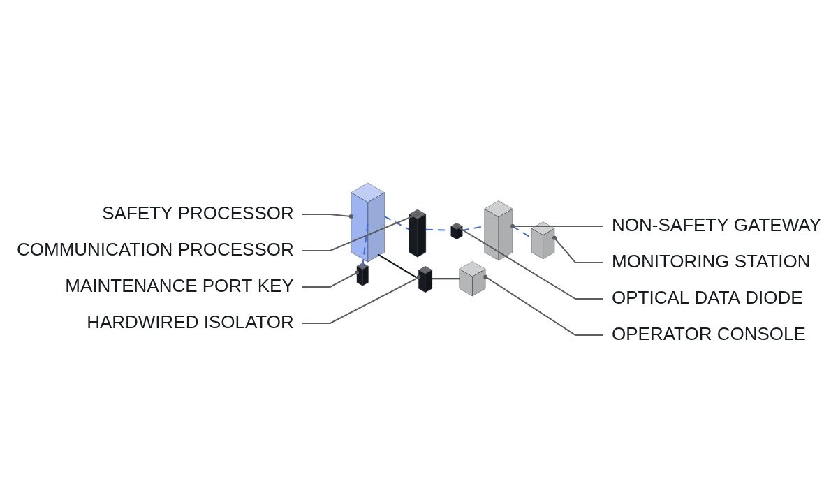
- □ Confirm the safety-to-non-safety link is physically transmit-only (for example, a data diode with only an optical transmitter). Physically absent receive circuitry is not the same as receive blocked in software.
- □ Confirm the safety processor never waits for transmission completion or a response. Transmission must be a write to a buffer, and done.
- □ Confirm by test that communication module failure (transmitter stopped, buffer full) does not lengthen or stall the safety processor’s execution cycle.
- □ Confirm signals that must go from non-safety to safety (for example, operator manual actions) pass through hardwired contacts or isolation devices, not a network.
- □ Confirm maintenance and configuration ports are cut off during operation by a physical key switch or cable disconnection, and that connection status is indicated in the control room.
- □ If there is communication between safety trains, confirm a communication failure in one train cannot affect the function of another.
Three conditions for one-way to hold
The first is the physical layer. A data diode, with an optical transmitter and receiver connected in one direction only, has no medium over which a reverse signal could travel. A configuration that blocks the reverse direction with firewall or switch settings becomes two-way after one configuration error or one equipment fault.
The second is the protocol. Protocols like TCP that require connection setup and acknowledgments do not run over a physical one-way link. One-way segments therefore use UDP-style broadcast transmission or dedicated frames, and the receiver does its own error detection with CRC and sequence numbers. Since a lost frame cannot be re-requested, the design assumes it will be replaced by the next cycle’s data.
The third is execution independence, and it is the one most often missed. If the safety processor calls a send function and waits for completion, a transmitter failure affects the execution cycle even though the link is one-way. The principle is that the safety processor writes to shared or dual-port memory and moves on, while a separate communication processor handles transmission asynchronously.
Architecture flowchart
- At the end of its execution cycle, the safety processor writes output data to dual-port memory.
- On its own independent cycle, the communication processor reads the memory and builds a frame with a sequence number and CRC.
- The frame goes over a transmit-only optical link (data diode) to the non-safety gateway.
- The non-safety gateway checks CRC and sequence, judges loss and delay on its own, and attaches a data quality flag.
- Display, recording, and monitoring functions in the non-safety domain use only data whose quality flag has been checked.
Safety-side transmit pseudocode (IEC 61131-3 ST)
(* I/O MAP - safety processor side *)
(* %MW100~%MW131 : DPM_TX_AREA         - dual-port memory transmit area *)
(* %MW132        : DPM_TX_SEQ          - transmit sequence number *)
(* %I8.0         : DI_COMM_MOD_HEALTHY - communication module status (monitoring only) *)
(* %I8.1         : DI_MAINT_PORT_KEY   - maintenance port key switch in connect position (hardwired) *)
(* %Q6.0         : DO_COMM_FAULT_LAMP  - communication module fault indication *)
(* %Q6.1         : DO_MAINT_PORT_ALM   - maintenance port connected alarm *)

(* 1. Protection logic - runs every cycle regardless of communication status *)
PROTECTION_LOGIC();   (* trip decision is completed inside this function *)

(* 2. Transmit - write to memory and done. No wait for completion or response *)
DPM_TX_AREA := PROTECTION_STATUS_SNAPSHOT;
DPM_TX_SEQ  := DPM_TX_SEQ + 1;

(* 3. Communication module fault is indication only. No feedback into protection logic *)
DO_COMM_FAULT_LAMP := NOT DI_COMM_MOD_HEALTHY;

(* 4. Maintenance port - connection itself is controlled by hardware key, logic only indicates *)
DO_MAINT_PORT_ALM := DI_MAINT_PORT_KEY;

(* PROHIBITED: IF NOT DI_COMM_MOD_HEALTHY THEN ... change protection logic ... END_IF; *)
(* PROHIBITED: WAIT_TX_DONE(); or any loop waiting for a receive response *)
The two prohibited lines at the end are the point of this article. The moment communication module status becomes a condition in the protection logic, the communication boundary is no longer a boundary. It is safer to lock “monitor, but never feed back” in as a code review checklist item.
Comparison of separation methods
| Method | Basis for reverse block | Config error impact | Where used |
|---|---|---|---|
| Firewall rules | Software settings | Can become two-way | Between non-safety zones |
| One-way gateway (SW) | Software implementation | Implementation defects | Between non-safety zones |
| Optical data diode | Physical absence | Reverse impossible | Safety to non-safety |
| Hardwired isolation | Electrical isolation | Not applicable | Non-safety to safety signals |
The “where used” column gives the conclusion. At the safety boundary, use only methods whose reverse-block basis is physical absence, and use software-based separation for defense in depth between non-safety zones. Signals that must enter safety from non-safety go through hardwired isolation devices, without creating a network path.
Boundary conditions
This principle becomes a burden as functions that need to push data into the safety system multiply. Setpoint changes, online diagnostics, and software updates inherently require a reverse path. Allowing them over the network during operation breaks the one-way principle, so those tasks have to be tied, by operating procedure and by hardware, to a state where the channel is bypassed and the maintenance port is connected with a physical key. The actual error rate and latency of the link vary with the installation environment and require waveform analysis and field measurement.
The single decision rule: accept a boundary as one-way only when you can show by test that pulling the communication module changes neither the protection execution cycle nor the trip decision.