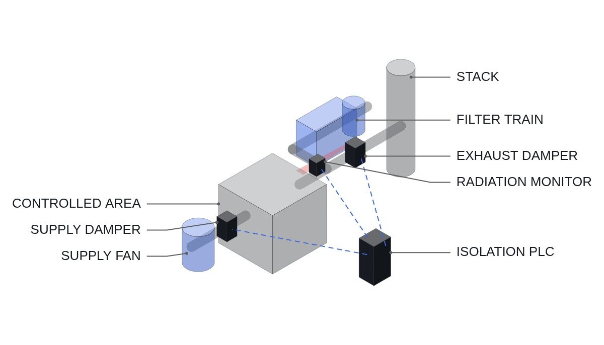
The short version: the most common design error in interlocks that isolate ventilation on a radiation monitor signal is not in the signal logic but in the order of isolation. Close the exhaust damper first and let the supply fan run even a few seconds longer, and the radiologically controlled area flips from negative to positive pressure, pushing contaminated air toward uncontrolled areas. So the isolation sequence has to enforce, by interlock, the order “stop supply, divert exhaust to the filter train, then close the normal exhaust path”, and how to treat monitor failure signals is decided only after that order is secured.
Safety interlocks come first
This article covers the link between non-safety process radiation monitors and normal ventilation isolation in radiologically controlled areas such as the auxiliary building and fuel handling area. Safety-grade isolations driven by engineered safety feature actuation signals, such as containment isolation or main control room emergency ventilation, are separate systems and are not covered here. Even at non-safety grade, the following conditions must hold.
- □ Enforced isolation order: do not close the exhaust path before the supply fan is confirmed stopped (or supply damper closed). Do not use parallel command structures that could violate the order.
- □ Filter train first: when diverting exhaust to the filter train (HEPA and charcoal), confirm the filter train fan is running before closing the normal exhaust damper. There must be no interval with both paths closed.
- □ Monitor failure goes to the safe side: loss of monitor signal, detector high-voltage fault or low sample flow is judged “unable to measure” and handled as isolation or alarm per the design basis. It is never treated as “reading zero”.
- □ Manual reset only: isolation does not reset automatically when radiation levels fall; the operator resets it after confirmation.
- □ Document the priority when fire detection damper closure and radiation isolation conflict.
- □ EMO circuits cut fan power through hardwiring; the PLC only monitors status.
Monitor signal logic compared
Non-safety monitors are often single-channel, with two channels in areas of higher importance. The number of channels and the voting logic set the balance between spurious isolation and failure to isolate.
| Logic | Failure to isolate | Spurious isolation | When it fits |
|---|---|---|---|
| 1 channel, isolate on fault | Low | High (every detector fault isolates) | Areas where isolation is cheap |
| 1 channel, alarm on fault | High | Low | Areas with alternative monitoring |
| 1-out-of-2 | Very low | High | Where failure to isolate has large consequences |
| 2-out-of-2 | Medium | Low | Where spurious isolation hurts operations |
| 2 channels, degrade to 1 on fault | Low | Medium | Normal 2-channel operation, needs cover during maintenance |
The takeaway is in the last row. With two channels, the practical balance is 2-out-of-2 in normal operation to cut spurious isolations, degrading to the one remaining channel when one fails. Degrading by treating the failed channel as “normal” is prohibited; that effectively removes the isolation function.
Isolation sequence flowchart
- Isolation decision: the channel logic finds the isolation condition met (high level, or an unable-to-measure state that the design treats as an isolation trigger).
- Stop the supply fan and close the supply damper. Confirm fan stopped and damper closed limit switches.
- Start the filter train fan and open the filter inlet damper. Confirm fan running and differential pressure normal.
- Close the normal exhaust damper. Confirm closed limit.
- Area differential pressure: confirm negative pressure is held. Alarm if it is not established within the set time.
- If any step’s confirmation fails, do not proceed to the next step; alarm and hand the decision to the operator. The supply stop is maintained in every case.
ST pseudocode: order-enforced isolation logic
(* I/O MAP - auxiliary building exhaust radiation isolation, non-safety *)
(* %I7.0  DI_RM_CH1_HIGH        : monitor 1 high level *)
(* %I7.1  DI_RM_CH1_FAIL        : monitor 1 unable to measure - signal, HV, flow *)
(* %I7.2  DI_RM_CH2_HIGH        : monitor 2 high level *)
(* %I7.3  DI_RM_CH2_FAIL        : monitor 2 unable to measure *)
(* %I7.4  DI_SUPPLY_FAN_STOPPED : supply fan stopped *)
(* %I7.5  DI_SUPPLY_DMP_CLOSED  : supply damper closed limit *)
(* %I7.6  DI_FILTER_FAN_RUN     : filter train fan running *)
(* %I7.7  DI_FILTER_DMP_OPEN    : filter inlet damper open limit *)
(* %I8.0  DI_NORMAL_EXH_DMP_CLOSED : normal exhaust damper closed limit *)
(* %I8.1  DI_ISO_RESET_PB       : isolation manual reset *)
(* %IW700 AI_ZONE_DP_PA         : area differential pressure, Pa, negative is suction *)
(* %Q7.0  DO_SUPPLY_FAN_STOP    : stop supply fan *)
(* %Q7.1  DO_SUPPLY_DMP_CLOSE   : close supply damper *)
(* %Q7.2  DO_FILTER_FAN_START   : start filter train fan *)
(* %Q7.3  DO_FILTER_DMP_OPEN    : open filter inlet damper *)
(* %Q7.4  DO_NORMAL_EXH_DMP_CLOSE : close normal exhaust damper *)
(* %Q7.5  DO_ISO_SEQ_ALARM      : isolation sequence fault alarm *)

(* 1. Channel logic - 2-out-of-2, degrade to remaining channel on fault *)
IF DI_RM_CH1_FAIL AND DI_RM_CH2_FAIL THEN
    ISO_DEMAND := TRUE;                           (* both unable to measure - isolate *)
ELSIF DI_RM_CH1_FAIL THEN
    ISO_DEMAND := DI_RM_CH2_HIGH;                 (* degraded - channel 2 alone *)
ELSIF DI_RM_CH2_FAIL THEN
    ISO_DEMAND := DI_RM_CH1_HIGH;
ELSE
    ISO_DEMAND := DI_RM_CH1_HIGH AND DI_RM_CH2_HIGH;
END_IF;

IF ISO_DEMAND THEN ISO_LATCH := TRUE; END_IF;     (* no automatic reset *)

(* 2. Step 1 - supply stop held throughout isolation *)
IF ISO_LATCH THEN
    DO_SUPPLY_FAN_STOP  := TRUE;
    DO_SUPPLY_DMP_CLOSE := TRUE;
END_IF;
STEP1_DONE := DI_SUPPLY_FAN_STOPPED AND DI_SUPPLY_DMP_CLOSED;

(* 3. Step 2 - filter train only after supply stop is confirmed *)
IF ISO_LATCH AND STEP1_DONE THEN
    DO_FILTER_FAN_START := TRUE;
    DO_FILTER_DMP_OPEN  := TRUE;
END_IF;
STEP2_DONE := DI_FILTER_FAN_RUN AND DI_FILTER_DMP_OPEN;

(* 4. Step 3 - close normal exhaust only once the filter path is established *)
IF ISO_LATCH AND STEP1_DONE AND STEP2_DONE THEN
    DO_NORMAL_EXH_DMP_CLOSE := TRUE;
END_IF;

(* 5. Step delay supervision - alarm if stuck, previous steps held *)
T_SEQ(IN := ISO_LATCH AND NOT DI_NORMAL_EXH_DMP_CLOSED, PT := T#60S);
IF T_SEQ.Q OR (ISO_LATCH AND DI_NORMAL_EXH_DMP_CLOSED AND (AI_ZONE_DP_PA > R_DP_NEG_MIN_PA)) THEN
    DO_ISO_SEQ_ALARM := TRUE;
END_IF;

(* 6. Manual reset - only once the isolation demand has cleared *)
IF DI_ISO_RESET_PB AND NOT ISO_DEMAND THEN
    ISO_LATCH := FALSE;
END_IF;
The 60 s step supervision and R_DP_NEG_MIN_PA are illustrative; real values come from damper actuator stroke times and the area’s design differential pressure. If the filter train fan fails to start, this logic does not close the normal exhaust and only raises an alarm. Whether to keep or close the normal exhaust at that point is an operator decision under the release path management rules, and the automatic logic deliberately does not make it.
Field inspection checklist
- □ Check each monitor with its check source and confirm the high-level signal reaches the PLC.
- □ Simulate signal wire disconnection, detector power loss and low sample flow separately and confirm each is judged “unable to measure”.
- □ In an isolation test, confirm from time-stamped records that the order is supply stop, filter start, then normal exhaust closure.
- □ Record area differential pressure throughout isolation to confirm it stays negative. Fluctuation in the differential pressure reading requires waveform analysis and field measurement.
- □ Confirm the behavior when fire damper closure and radiation isolation arrive together matches the documentation.
- □ Confirm isolation never resets automatically and resets only by manual reset.
Boundary conditions: when this design is wrong
First, when the isolation function is classified as safety grade. Once the function class rises, voting logic, channel independence and software verification must meet the class requirements of the IEC 61226 and IEC 61513 framework, and the non-safety PLC structure here cannot be used as is.
Second, small areas where supply and exhaust recirculate through one fan. The supply-then-exhaust order does not exist, and isolation is simply stopping the recirculation fan and sealing the area.
Third, monitors located downstream in the exhaust duct so that, after isolation, no sampled air flows past them. A level that seems to fall after isolation may just reflect zero flow, so it must not be the basis for a manual reset decision.
The single decision rule: judge an isolation interlock not by its voting logic but by whether the controlled area keeps negative pressure at every moment of the isolation.