The short answer first. Noise on nuclear safety system instrument signals is not something to cover with a software filter. A filter’s time constant adds directly to channel response time, and channel response time has to stay within the value assumed in the safety analysis. So the order is first reduce noise ingress through grounding, shielding, and cable separation, then filter only the residual noise, within the response time budget. Which noise enters where cannot be settled at the design stage, so the basis for judgment is left to waveform analysis and field measurement.
Start with the safety interlock conditions
Noise countermeasures can harm a safety function in two ways: a filter slows the response, or judgment logic added to reject noise also ignores a genuine abnormal signal. The interlock items are set to close off both paths.
- □ Confirm the time constants of every filter in the channel (sensor internal damping, transmitter setting, input module filter, software filter) have been summed and included in the channel response time budget.
- □ Confirm the design documents define whether out-of-range detection (open or short circuit) sends the channel to the trip direction or to “fault indication, then operator judgment.”
- □ Confirm rate-limit logic does not suppress a fast change in a real transient by mistaking it for noise, checked against the safety analysis transient curves.
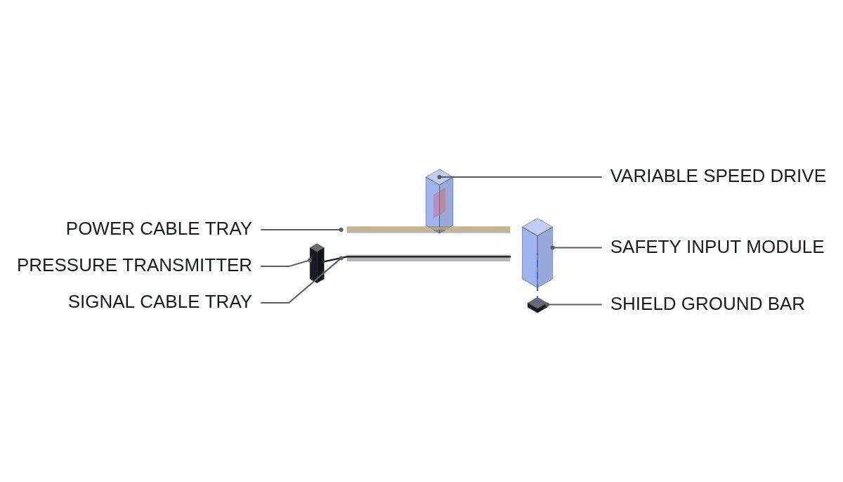
- □ Confirm safety channel signal cables run in trays and conduits separate from power cables.
- □ Confirm the wiring diagrams state where and how instrument ground and power ground are connected.
Countermeasures by ingress path
A 4-20 mA current loop is more noise-resistant than a voltage signal but remains vulnerable to common-mode noise and ground potential differences. Noise ingress falls into three broad paths: inductive and capacitive coupling from power cables, current driven by potential differences through ground loops, and high-frequency radiation from inverters, variable-speed drives, and similar equipment.
The shield grounding decision flips with frequency band. For low-frequency (power-frequency band) noise, grounding the shield at one end only, so no ground loop forms, is the better choice. For high-frequency noise, grounding at both ends or at multiple points, so the shield reaches ground by a short path, is the better choice. IEEE 1050 provides guidance on instrumentation and control equipment grounding in generating stations and leaves this choice to be matched to site conditions. Which band dominates is not a matter for calculation; it requires waveform analysis and field measurement.
One more item is the loop power common. If the 24V DC loop supply negatives of several channels are tied at one point and that common is grounded again somewhere else, the channels end up sharing each other’s ground currents. Noise on one channel then migrates to others, so from a channel independence standpoint as well, loop supplies and commons are better separated per channel. If channel separation is already in place, all that remains is confirming the common-mode voltage is within the signal isolator’s rating.
Field execution sequence
- Record the affected channel’s signal by operating state (shutdown, large motor starting, variable-speed drive running).
- Identify the noise frequency content in the recorded waveform. Distinguish power-frequency components from switching-frequency bands.
- If low-frequency components dominate, check for ground loops first (shield grounded at both ends, instrument common grounded at multiple points, and so on).
- If high-frequency components dominate, check routing near power cables and variable-speed drive output cables, and the shield termination method.
- After wiring and grounding changes, re-measure under the same conditions to confirm improvement.
- Only for the residual noise, consider a filter within the response time budget.
Signal quality pseudocode (IEC 61131-3 ST)
(* I/O MAP - safety channel A input processing *)
(* %IW40 : AI_PT_A_RAW_MA     - pressure transmitter loop current, mA *)
(* %Q7.0 : DO_CH_A_SIG_FAIL   - signal failure indication *)
(* %Q7.1 : DO_CH_A_ROC_ALM    - rate-of-change alarm (monitoring only) *)

(* 1. Range check - based on NAMUR NE 43 bands *)
(*    3.8 to 20.5 mA : measurement range (includes slight under/over-range of 4-20 mA) *)
(*    below 3.6 mA or above 21.0 mA : failure signal *)
X_SIG_FAIL := (AI_PT_A_RAW_MA < 3.6) OR (AI_PT_A_RAW_MA > 21.0);
DO_CH_A_SIG_FAIL := X_SIG_FAIL;

(* 2. Filter - time constant T_FILT within the ceiling derived from channel response time budget *)
X_FILT := X_FILT + (AI_PT_A_RAW_MA - X_FILT) * (T_SCAN / (T_FILT + T_SCAN));

(* 3. Rate of change - alarm only. Never suppress the value or freeze the previous value *)
X_ROC := ABS(AI_PT_A_RAW_MA - X_PREV) / T_SCAN;
DO_CH_A_ROC_ALM := X_ROC > R_ROC_TH;
X_PREV := AI_PT_A_RAW_MA;

(* 4. Bistable input - on signal failure the channel goes the direction set in the design documents *)
IF X_SIG_FAIL THEN
    X_CH_A_TRIP := B_FAIL_TO_TRIP;     (* design choice: TRUE = trip direction *)
ELSE
    X_CH_A_TRIP := SCALE_TO_ENG(X_FILT) >= R_TRIP_SP;
END_IF;
There is a reason item 3 handles abnormal rate of change as “alarm only.” Suppressing values with a rate limit treats a genuinely rapid pressure change as noise and delays the trip. Whether something is noise is for operators and maintenance staff to judge from waveforms, not for the protection logic to decide on its own.
Comparison of countermeasures
| Measure | Response time impact | Effective band | When to apply |
|---|---|---|---|
| Cable separation | None | All bands | First priority |
| Shield single-point ground | None | Low frequency | Ground loop confirmed |
| Shield both-end ground | None | High frequency | Radiated noise confirmed |
| Signal isolator | Small | Common mode | Ground potential difference confirmed |
| Software filter | Yes | Set band | Residual only |
The rule is to apply measures with “None” in the response time column first. Filters and signal isolators consume response time budget, so use them only on the noise that remains after wiring and grounding work is done. Reverse the order and the noise disappears along with the response time margin.
Boundary conditions
The shield grounding decision flips on the noise frequency band. If a problem is judged to be low-frequency and the shield is switched to single-point grounding, but the dominant component is actually high-frequency from a variable-speed drive, the noise can get worse. And on a channel whose response time budget is already tight, no filter can be used at all, leaving cable rerouting as the only option. In either case, do not finalize a countermeasure without comparing before-and-after waveforms under the same conditions.
The single decision rule: confirm the dominant noise frequency band from measured waveforms, reduce it first with measures that cost no response time, and use a filter only within whatever response time budget remains.