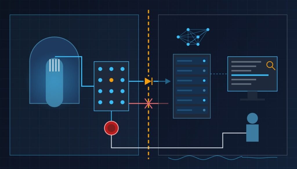
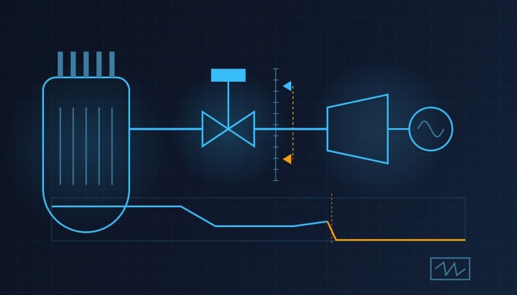
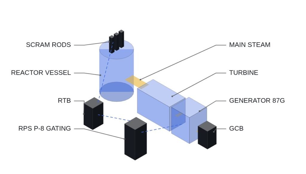
The main review for Standard Design Approval (SDA) of the innovative small modular reactor (i-SMR, Innovative Small Modular Reactor) has begun. The Nuclear Safety and Security Commission has completed its document adequacy review of the 700 MW-class design and moved into full technical review. The real issue in this review is how far the regulator will accept boron-free operation and the in-vessel control rod drive mechanism (CRDM, Control Rod Drive Mechanism).
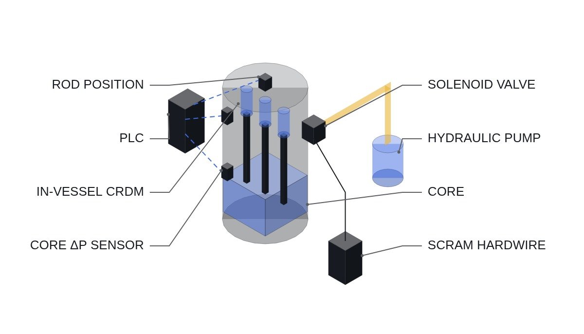
Licensing review is logic on paper, but CRDM interlock design ultimately comes down to field wiring and signal timing.
On 4 March 2026, the Nuclear Safety and Security Commission held an “i-SMR review preparation workshop” and announced that it had begun the first SDA review of the 700 MW-class i-SMR. The Korea Institute of Nuclear Safety (KINS) said it would conduct a six-month document adequacy review of the application documents submitted by the developer from 27 February 2026 before starting the main review, and the start of the main review was in fact reported around the end of August, when that deadline passed. The review proceeds with KINS raising questions on design safety and technical validity issue by issue and the developer responding, and the industry expects it to take at least about three years.
Preconditions: The CRDM interlock signal names and setpoints discussed in this article are concept examples reconstructed from published patent literature and press reports on the regulatory review, and may differ from the RPS (Reactor Protection System) setpoints and trip logic actually adopted by the i-SMR Technology Development Agency. Actual core differential pressure trip values, solenoid response times and similar data require confirmation from the reactor designer’s non-public design documents.
Safety interlock check order (top priority)
- Monitoring of differential pressure (ΔP) across the core barrel — raise an alarm first if the differential pressure leaves the range required to drive the hydraulic cylinders, and stop CRDM drive automatically if the excursion persists.
- Solenoid-poppet valve response check — because an external solenoid regulates hydraulic supply through a poppet valve, isolate the affected control rod train immediately if the solenoid energisation signal and the valve position feedback disagree.
- Cross-check of control rod position sensors — if position feedback and the drive pulse count disagree (step mismatch), treat it as an abnormal core power distribution and force a switch from load-following mode to normal operation mode.
- Check of the passive safety system natural circulation path — periodically self-diagnose that a path allowing cooling by gravity and natural circulation without power supply is available; raise a top-priority alarm on failure.
- EMO (emergency stop) — the principle is a configuration in which hardware wiring directly acts on the reactor trip (SCRAM) signal; designs that replace or bypass the EMO function with software logic alone are not covered on this site.
CRDM hydraulic drive I/O map (concept example)
| Signal | I/O address | Type | Operating condition |
|---|---|---|---|
| Core differential pressure sensor | AI201 | AI | Differential pressure ΔP; sets AI201_ALARM on leaving normal range |
| Solenoid energisation signal | DO201 | DO | Energised individually per control rod train, continuously monitored |
| Poppet valve position feedback | AI202 | AI | Correlation with DO201 verified within the delay time |
| Control rod position feedback | AI203 | AI | Step error monitored against drive pulse count |
| Reactor trip (SCRAM) hardwire | DI201 | DI | Wired directly to the RPS trip relay without passing through PLC logic |
The implication of this checklist is clear. The in-vessel CRDM places the hydraulic drive inside the reactor vessel to reduce piping penetrations, and in exchange accepts the monitoring burden of keeping three signals — core differential pressure, solenoid response and position feedback — consistent at the same time.
PLC logic snippet (IEC 61131-3 Structured Text pseudocode, concept example)
IF DI201 = 1 THEN
    (* hardwired SCRAM signal received - PLC only indicates status; the trip itself is performed directly by the hardware relay *)
    DO201 := 0;
ELSIF (AI201 < DP_LOW_LIMIT) OR (AI201 > DP_HIGH_LIMIT) THEN
    (* core differential pressure abnormal - stop drive of the affected CRDM train and alarm; setpoints to be verified *)
    DO201 := 0;
    AI201_ALARM := 1;
ELSIF ABS(AI202 - DO201_EXPECTED) > VALVE_MISMATCH_LIMIT THEN
    (* solenoid-poppet valve response mismatch - isolate the affected train *)
    DO201 := 0;
    VALVE_MISMATCH_ALARM := 1;
ELSE
    (* normal - keep monitoring correlation between position feedback and pulse count *)
    ROD_POSITION_CHECK := 1;
END_IF;
External vs in-vessel CRDM: character of the monitored signals
Where the interlock burden of an in-vessel CRDM comes from becomes clear when it is set beside the conventional arrangement. The table compares the character of the monitoring structure only, not setpoints.
| Item | External CRDM | In-vessel hydraulic CRDM |
|---|---|---|
| Drive location | Outside the reactor head | Inside the reactor vessel |
| Pressure boundary penetrations | One per drive shaft | Reduced |
| Main monitored signals | Drive coil current, position indication | Core differential pressure, solenoid response, position feedback |
| Fault judgement | Direct check of drive electrical signals | Inferred from correlation of indirect signals |
| Maintenance access | Relatively easy | Limited, inside the vessel |
Implication: the in-vessel design eases the pressure-boundary burden by reducing penetrations, but because the drive cannot be observed directly it hands fault judgement to the correlation of indirect signals; what the review really tests is the validity of the cross-signal consistency logic, not the accuracy of any single signal.
One practical criterion is easy to miss here. The more a design relies on indirect signals, the more a signal-quality diagnosis must sit in front of the interlock. If the AI201 differential pressure signal goes out of range because of a broken wire, it triggers an unnecessary CRDM stop; if the sensor instead sticks at a value inside the normal range, it hides a real pressure abnormality. Alongside broken-wire and out-of-range detection, a stuck condition, where a signal that should move during operation stays unchanged for a set time, must be split out as its own alarm so that process abnormalities can be told apart from instrument faults. The time basis for that judgement is an item to confirm with the reactor designer’s documents.
- [ ] Is broken-wire and out-of-range detection for each of AI201, AI202 and AI203 placed ahead of process-abnormality judgement?
- [ ] Is there a separate alarm that detects a signal stuck inside the normal range?
- [ ] Is CRDM train behaviour (hold or isolate) on an instrument fault defined for each operating mode?
- [ ] Does the DI201 SCRAM hardwired path remain independent of this diagnostic logic?
Boundary conditions
Boundary conditions — responding to field variables: If boron-free operation is approved by the regulator, this i-SMR will be the first case among pressurised water reactor SMRs. But there is precedent: neither NuScale Power, which in 2023 became the first to receive SMR design certification, nor Holtec, which plans to build an SMR at the Palisades site, has had boron-free operation accepted. The final interlock configuration may therefore change depending on the outcome of further consultation with the regulator. Actual trip setpoints and response times require waveform analysis and field measurement. The selection criterion comes down to one point: whether consistency among the three signals — core differential pressure, solenoid response and position feedback — can be secured is the practical gateway to passing the review.
References
- Electric Times, “SMR review begins… three-year contest over boron-free operation, passive systems and load following”, 2026-03-05, https://www.electimes.com/news/articleView.html?idxno=365728
- Electric Times, “Main review of innovative SMR begins… boron-free operation and in-vessel CRDM under scrutiny”, August 2026, https://www.electimes.com/news/articleView.html?idxno=371798
- KR101880782B1, Nuclear reactor internal hydraulic control rod drive mechanism assembly, Westinghouse Electric Company LLC, filed 2011-12-09 / registered 2018-07-20, legal status: Expired – Fee Related (anticipated expiry 2031-12-09)