The short answer first. What makes safety bus transfer on a loss of offsite power (LOOP) hard is not the case where voltage vanishes completely. It is degraded voltage: voltage that sags to an ambiguous level and stays there. Complete loss just needs fast detection. Degraded voltage, detected too fast, throws away offsite power every time a large motor starts; detected too slowly, it lets safety motors overheat at low voltage. So undervoltage detection is split into two levels, “loss” and “degraded,” and the center of the design is placing the degraded-level time delay between the motor-starting voltage dip duration and the motor thermal limit.
Start with the safety interlock conditions
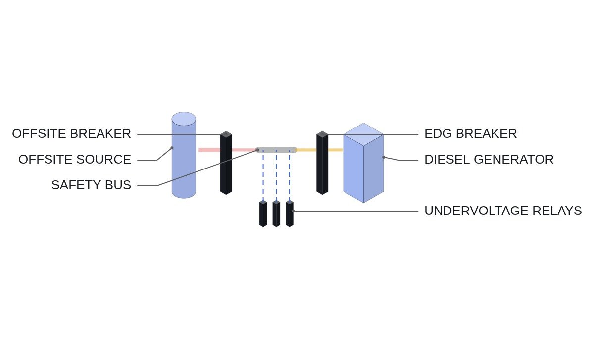
A safety bus transfer means “drop source A, connect source B.” The first things to prevent are asynchronous paralleling of the two sources and closing another source onto a bus that still carries residual voltage. Both are built as hardwired breaker interlocks, and the logic manages sequence on top of them.
- □ Confirm a hardwired mutual interlock between the offsite supply breaker and the EDG breaker (closing one opens the other’s close circuit).
- □ Confirm the undervoltage relays (ANSI 27) have independent channels per train and decide by coincidence logic (for example 2-out-of-3 or 2-out-of-4). A single blown potential transformer (PT) fuse must not transfer the bus.
- □ Confirm PT fuse failure monitoring exists as a separate alarm.
- □ Confirm a condition verifies bus residual voltage has decayed sufficiently before the alternate source closes (residual voltage relay or time delay).
- □ Confirm the load shedding signal is tied to the transfer and clears after transfer.
Two-level undervoltage detection
Level 1 is loss of voltage. When bus voltage drops heavily, after a short delay the offsite supply breaker opens and EDG start and load shedding begin. The delay only needs to be long enough to ignore the momentary dip during bus fault clearing.
Level 2 is degraded voltage: voltage below rated but above the loss threshold, sustained. It occurs when grid-side voltage regulation fails or offsite line impedance rises, among other causes. In this state, safety motors will start but with too little torque, so they accelerate slowly, draw high current, and approach their thermal limits.
The Level 2 delay has to sit between two boundaries. The lower bound must be longer than the time the bus spends below the degraded threshold during a normal large-motor start before recovering. The upper bound must be shorter than both the time a safety motor can tolerate degraded voltage without damage and the safety-function initiation time assumed in the safety analysis. If the lower bound is longer than the upper bound, no setting will fix it; the transformer taps or motor starting method have to change.
Transfer flowchart
- Determine whether undervoltage channel coincidence is met (Level 1 or Level 2).
- For Level 2, monitor for voltage recovery during the delay timer. If it recovers, cancel the transfer.
- Command the offsite supply breaker open and confirm open.
- Command bus load shedding. Issue the EDG start signal.
- Confirm residual voltage decay (residual voltage relay or delay).
- After the EDG reaches rated, close the EDG breaker onto the dead bus.
- Clear load shedding and hand control to the load sequencer.
Transfer logic pseudocode (IEC 61131-3 ST)
(* I/O MAP - safety bus train A *)
(* %I4.0~%I4.2 : DI_UV1_CH1 ~ DI_UV1_CH3   - Level 1 (loss) relay contacts, 3 channels *)
(* %I4.3~%I4.5 : DI_UV2_CH1 ~ DI_UV2_CH3   - Level 2 (degraded) relay contacts, 3 channels *)
(* %I4.6 : DI_OFFSITE_BRK_OPEN *)
(* %I4.7 : DI_RESIDUAL_V_LOW               - residual voltage decayed *)
(* %I5.0 : DI_PT_FUSE_FAIL                 - PT fuse failure monitor *)
(* %I5.1 : DI_EDG_BRK_CLOSED               - EDG breaker closed *)
(* %Q3.0 : DO_OFFSITE_BRK_TRIP *)
(* %Q3.1 : DO_LOAD_SHED *)
(* %Q3.2 : DO_EDG_START *)
(* %Q3.3 : DO_BUS_TRANSFER_PERMIT          - EDG breaker close permit (ANDed with hardwired interlock) *)

(* 1. Channel coincidence 2/3 *)
X_UV1 := (DI_UV1_CH1 AND DI_UV1_CH2) OR (DI_UV1_CH2 AND DI_UV1_CH3) OR (DI_UV1_CH1 AND DI_UV1_CH3);
X_UV2 := (DI_UV2_CH1 AND DI_UV2_CH2) OR (DI_UV2_CH2 AND DI_UV2_CH3) OR (DI_UV2_CH1 AND DI_UV2_CH3);

(* 2. Delays - T_UV1 short (ignore fault-clearing dip); motor start dip < T_UV2 < motor thermal limit *)
TON_UV1(IN := X_UV1, PT := T_UV1);
TON_UV2(IN := X_UV2, PT := T_UV2);
X_LOOP := TON_UV1.Q OR TON_UV2.Q;

(* 3. Separate offsite, shed load, start EDG - sealed in *)
IF X_LOOP THEN X_TRANSFER_LATCH := TRUE; END_IF;
DO_OFFSITE_BRK_TRIP := X_TRANSFER_LATCH;
DO_EDG_START        := X_TRANSFER_LATCH;
DO_LOAD_SHED        := X_TRANSFER_LATCH AND NOT DI_EDG_BRK_CLOSED;

(* 4. EDG close permit - offsite open confirmed + residual voltage decayed *)
DO_BUS_TRANSFER_PERMIT := X_TRANSFER_LATCH AND DI_OFFSITE_BRK_OPEN AND DI_RESIDUAL_V_LOW;

(* 5. PT fuse failure is alarm only - the affected channel goes to trip or non-trip as defined by relay design *)
X_PT_FUSE_ALM := DI_PT_FUSE_FAIL;
Comment 5 is a design choice. If a blown-fuse channel goes to the trip direction, one false signal from either remaining channel transfers the bus; if it goes to non-trip, both remaining channels must operate. It is the same structure of judgment as RPS channel bypass, and it must match the plant’s protection philosophy.
Characteristics by detection level
| Item | Level 1 loss | Level 2 degraded |
|---|---|---|
| Target event | Offsite supply lost | Sustained low voltage |
| Delay | Short | Relatively long |
| Delay lower bound | Fault-clearing dip | Large motor start dip |
| Delay upper bound | Safety function start time | Motor thermal limit, analysis |
| Result if wrong | Unneeded transfer | Unneeded transfer or motor damage |
Read this table by comparing the lower and upper bounds in the Level 2 column. There has to be a window between the two to set a value at all; if there is none, the fix is not in relay settings but in the power system design (transformer taps, motor starting method, cable sizing).
Field verification items
The depth and duration of the bus voltage dip during a large safety motor start are not settled by calculation alone. Offsite system impedance changes with grid operating conditions, so record bus voltage waveforms during start tests and use them as the basis for the Level 2 lower bound. This requires waveform analysis and field measurement, and must be rechecked when grid conditions change.
The same goes for residual voltage decay. Induction motors on the bus keep spinning on inertia and generate residual voltage, and the decay rate depends on load makeup. If a time delay is used instead of a residual voltage relay, that delay must be based on a measured decay curve.
Boundary conditions
This two-level design goes wrong when there is no window between the degraded-voltage lower and upper bounds. With a weak offsite system, large-motor start dips last longer; the longer the Level 2 delay, the less protection margin the safety motors have, and the shorter it is, the more unneeded transfers occur on starts. Moving the setting either way increases one risk, so setting adjustment is not the answer.
The single decision rule: solve it with two-level settings only when the measured maximum motor-start dip duration is clearly shorter than the motor’s undervoltage withstand time; otherwise, change the power system design first.