The short answer first. In a safety-grade (Class 1E) 125V DC system, battery capacity is set by the load duty cycle, and charger capacity is set by “normal load plus recharge within a specified time.” Size the two separately and the numbers work, but the point where practical judgment splits is elsewhere: the period when the battery is disconnected for maintenance and the charger alone holds up the DC bus. The battery is the charger’s output filter and the buffer for transient loads, so whether that period is allowed decides both the charger specification (whether it is rated to run without a battery) and the operating restrictions.
Start with the safety interlock conditions
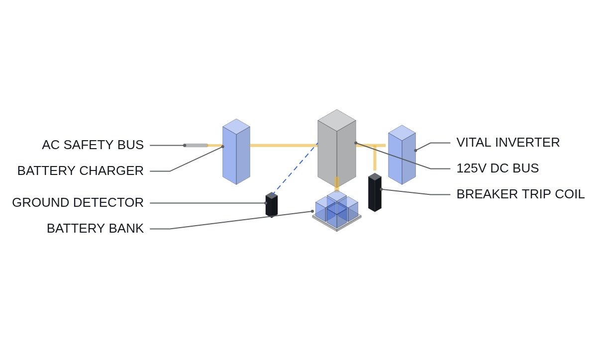
The 125V DC system is the “last source” for safety functions: breaker trip and close coils, protective relays, inverters feeding uninterruptible instrument power, EDG controls, and initial field flashing. So the interlock review looks first at keeping the DC bus from being lost, before looking at what disconnects it.
- □ Confirm each train’s DC system (battery, charger, distribution panel) is electrically and physically separated from the other trains (independence per IEEE 384).
- □ If there is a DC bus cross-tie breaker between trains, confirm it is interlocked open in normal operation and that operating restrictions prevent both trains from being exposed to a single fault while tied.
- □ Confirm opening the battery main breaker (or fused switch) raises an immediate control room alarm. This eliminates running without knowing the battery is disconnected.
- □ Confirm the ground detector on the ungrounded DC system monitors continuously and alarms to the control room.
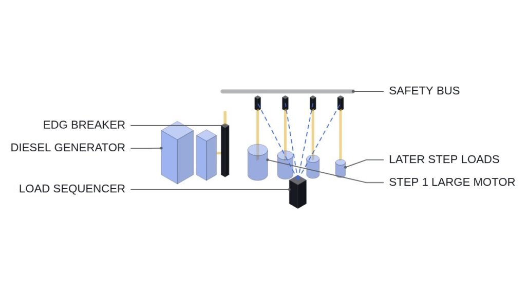
- □ Confirm the charger’s AC input is fed from the same train’s safety bus and is included in an EDG load sequence step.
Battery capacity is set by the duty cycle
The input to battery sizing is the load current profile from loss of AC power to the end of the specified coping time. Loads fall into three types: momentary loads (short high-current events such as breaker coil operation and EDG field flashing), continuous loads (inverters, relays, indicating lights), and non-continuous loads (emergency lighting, DC motors, and other loads that run only for part of the profile).
IEEE 485 gives the lead-acid battery sizing procedure: split the profile into sections, sum the required capacity, then apply correction factors. The typical corrections are temperature correction for the lowest electrolyte temperature, an aging factor for end-of-life capacity loss (commonly 1.25), and a design margin. An aging factor of 1.25 means “the battery still covers the duty cycle at end of life, when capacity has fallen to 80% of rated.”
Cell count and voltage window are worked backward from the load’s allowable voltage. Assumption: 60 lead-acid cells, end-of-discharge voltage 1.75 V/cell, float 2.25 V/cell. Bus voltage at end of discharge is 60 × 1.75 = 105 V, and on float 60 × 2.25 = 135 V. This 105 to 135 V window (including cable voltage drop) must fall inside the DC loads’ allowable input range, and the equalize voltage (manufacturer’s value × 60 cells) must separately be checked against the loads’ maximum allowable voltage.
Sizing the charger
In normal operation, the charger must supply all continuous load while recharging a discharged battery within a specified time. The formula widely used in plant DC system design is as follows.
Charger rated current A = L + (k × C) / H, where L is continuous load current, C is the capacity removed by discharge (Ah), H is the target recharge time (h), and k is a charging efficiency factor (typically 1.1 for lead-acid).
Assumption: L = 50 A, C = 400 Ah, H = 12 h, k = 1.1. A = 50 + (1.1 × 400) / 12 = 50 + 36.7 = 86.7 A. Choose the next standard rating above this (for example, a 100 A class) and confirm the current limit setting does not cap below this value. The numbers here are only a worked example; the actual L, C, and H come from the plant’s duty cycle and licensing conditions.
DC bus monitoring pseudocode (IEC 61131-3 ST)
(* I/O MAP - 125V DC train A monitoring (monitoring only, no tripping action) *)
(* %IW20 : AI_DC_BUS_V         - DC bus voltage, V *)
(* %IW21 : AI_BATT_I           - battery current, A (+ charge / - discharge) *)
(* %IW22 : AI_CHGR_I           - charger output current, A *)
(* %IW23 : AI_GND_DET_POS      - positive-to-ground insulation index *)
(* %IW24 : AI_GND_DET_NEG      - negative-to-ground insulation index *)
(* %I6.0 : DI_BATT_BRK_CLOSED  - battery main breaker closed *)
(* %I6.1 : DI_CHGR_AC_FAIL     - charger AC input lost *)
(* %Q4.0 : DO_DC_UV_ALM        - bus undervoltage alarm *)
(* %Q4.1 : DO_DC_OV_ALM        - bus overvoltage alarm (including equalize overvoltage) *)
(* %Q4.2 : DO_BATT_DISCONN_ALM *)
(* %Q4.3 : DO_GND_FAULT_ALM *)
(* %Q4.4 : DO_BATT_DISCHARGE_ALM *)

(* 1. Voltage window - R_V_LOW, R_V_HIGH derived from load allowable voltage *)
DO_DC_UV_ALM := AI_DC_BUS_V < R_V_LOW;
DO_DC_OV_ALM := AI_DC_BUS_V > R_V_HIGH;

(* 2. Battery disconnected - alarm the charger-only state immediately *)
DO_BATT_DISCONN_ALM := NOT DI_BATT_BRK_CLOSED;

(* 3. Battery discharging while AC input is healthy = charger fault or overload *)
TON_DISCH(IN := (AI_BATT_I < R_DISCH_TH) AND NOT DI_CHGR_AC_FAIL, PT := T_DISCH);
DO_BATT_DISCHARGE_ALM := TON_DISCH.Q;

(* 4. Ground - alarm on insulation loss on either pole, no tripping *)
DO_GND_FAULT_ALM := (AI_GND_DET_POS < R_GND_TH) OR (AI_GND_DET_NEG < R_GND_TH);
(* Ungrounded DC can run with one ground; the second causes coil misoperation, so start tracing at the first *)
Logic item 3 is the most useful in practice. If AC input is normal but battery current stays in the discharge direction for a set time, the charger output is not keeping up with the load or the charger has an internal fault. It flags the problem before the bus voltage alarm does, buying response time before the undervoltage alarm arrives.
Charger type comparison
| Item | Standard charger | Battery-eliminator rated |
|---|---|---|
| Output ripple | Assumes battery absorbs | Limited by own filter |
| Transient load response | Shared with battery | Charger alone |
| Battery-out maintenance | Restricted or not allowed | Conditionally allowed |
| Equipment cost | Lower | Higher |
| AC loss while battery out | DC bus lost at once | DC bus lost at once |
The last row shows the limit of this judgment. A higher-rated charger solves ripple and transient response, but if AC power is lost while the battery is disconnected, the DC bus is lost immediately with any charger. So whether battery-out maintenance is allowed must be decided together with a spare battery or cross-train tie conditions, not by charger rating alone.
Boundary conditions
This judgment goes wrong when the duty cycle itself changes. If the coping time requirement increases, or new inverters and digital instrumentation are added to the DC loads, continuous load L rises and both battery and charger capacity fall short at once. Using up the 1.25 aging factor to absorb load growth is the same as giving up the end-of-life capacity guarantee. The actual sensitivity of ground detection also depends on bus leakage capacitance and load makeup, and requires waveform analysis and field measurement.
The single decision rule: if battery-out maintenance must be allowed, choose a charger rated to operate without a battery; if not, use a standard charger with an operating restriction prohibiting battery disconnection.