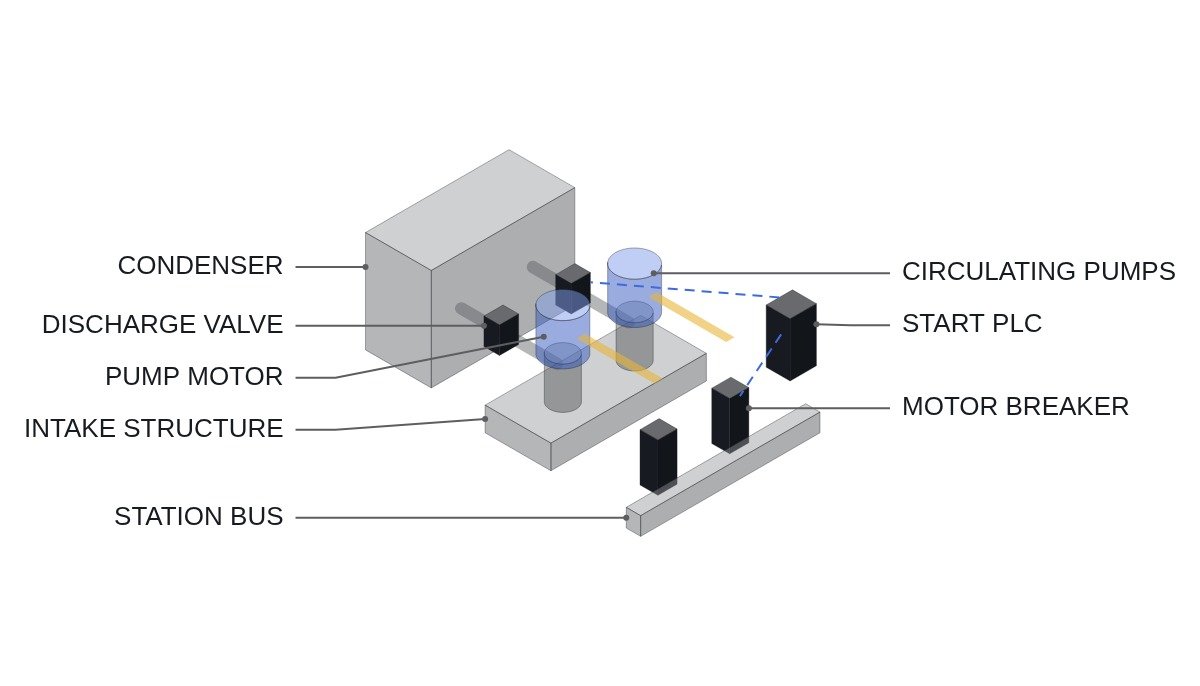
The short version: coordinating the start of multi-megawatt medium-voltage motors such as a nuclear plant’s circulating water pumps is less about “how many, at what interval” and more about whether the station bus voltage at the instant of starting stays above the re-acceleration limit of the other running motors. Pump type adds a second condition. Axial-flow and mixed-flow pumps draw more power at shutoff with the discharge valve closed, not less, so dragging out a closed-valve start brings motor overload and piping transients together. The start interlock has to tie bus voltage margin and valve opening time into one sequence.
Safety interlocks come first
The circulating water system maintains condenser vacuum, so its stop interlocks bear more directly on generation continuity than its start interlocks. Conditions for both are listed together.
- □ No start with the motor protection lockout (86M) operated, high winding temperature or high bearing temperature. These are hardwired series contacts in the start circuit.
- □ Start count limit: block starts beyond the manufacturer’s permitted cold and hot starts. The PLC calculates time since stop and uses it as a permissive.
- □ Bus voltage pre-check: bus voltage above the start lower limit, and no other large motor on the same bus currently starting.
- □ Discharge valve position: start only at the start position appropriate to the pump type. If the valve does not reach run position within a set time after start, stop the pump.
- □ Last circulating water pump stop restriction: with condenser vacuum established and the turbine on load, a manual stop command for the last pump requires a confirmation step. A protective stop (86M) acts immediately regardless.
- □ EMO circuits open the motor breaker through hardwiring; the PLC only monitors status.
Starting methods and bus voltage impact
Direct-on-line starting current for a large induction motor is several times rated, and the exact multiple and power factor must come from the manufacturer’s starting data. Bus voltage dip can be approximated from the ratio of starting kVA to bus short-circuit capacity. Assumption: bus short-circuit capacity 250 MVA, motor rating 3,000 kW, efficiency 0.95, power factor 0.88, starting current multiple 6. Rated input is 3,000 / (0.95 × 0.88) ≈ 3,590 kVA, starting kVA is about 21.5 MVA, and the approximate dip is 21.5 / (250 + 21.5) ≈ 7.9%.
| Method | Start current | Start torque | When it fits |
|---|---|---|---|
| Direct-on-line | Highest | Highest | Ample bus fault level, dip within limits |
| Reactor start | Reduced | Falls with voltage squared | Dip slightly over the limit |
| Autotransformer start | Lower still | Proportional to tap voltage squared | Weak bus, low load torque |
| Variable-speed drive | Within rating | Controllable | Flow control benefit outweighs equipment cost |
The takeaway: even if the calculated dip is within limits, the real dip only shows up once you include the running motors on the same bus slowing at that instant and then re-accelerating together. Most of the gap between calculated and measured dip is that re-acceleration load, so the starting method is best finalized after seeing measured waveforms.
Circulating water pump start flowchart
- Start permissive: 86M not operated, start count margin available, bus voltage normal, no other large motor starting on the same bus.
- Move the discharge valve to start position (closed or partly open depending on pump type) and confirm.
- Confirm auxiliaries such as lubrication and cooling water.
- Close the breaker and start the acceleration supervision timer.
- Start completion: if current falls into the running range within the set time, the start is complete; otherwise declare start failure and open the breaker.
- Open the discharge valve to run position. If it does not get there within the set time, stop the pump.
- Permit the next pump start only after bus voltage recovery is confirmed.
ST pseudocode: start permissive and valve coordination
(* I/O MAP - circulating water pump CWP-A start coordination *)
(* %I6.0  DI_86M_TRIP            : motor protection lockout *)
(* %I6.1  DI_CWP_A_52A_CLOSED    : motor breaker closed *)
(* %I6.2  DI_VALVE_START_POS     : discharge valve at start position *)
(* %I6.3  DI_VALVE_RUN_POS       : discharge valve at run position *)
(* %I6.4  DI_OTHER_MOTOR_STARTING: another large motor starting on same bus *)
(* %I6.5  DI_START_PB            : start command *)
(* %I6.6  DI_EMO_STATUS          : EMO status - monitoring only *)
(* %IW600 AI_BUS_V_PCT           : station bus voltage, % *)
(* %IW601 AI_MOTOR_I_A           : motor current, A *)
(* %IW602 AI_MIN_SINCE_STOP      : time since stop, min *)
(* %Q6.0  DO_CWP_A_CLOSE         : motor breaker close command *)
(* %Q6.1  DO_CWP_A_TRIP          : motor breaker open command *)
(* %Q6.2  DO_VALVE_OPEN_CMD      : discharge valve to run position *)
(* %Q6.3  DO_START_FAIL_ALM      : start failure alarm *)

(* 1. Start permissive - protection, start count, bus voltage, no simultaneous start *)
START_PERMIT := NOT DI_86M_TRIP
                AND (START_COUNT_HR < R_MAX_STARTS_HR)
                AND (AI_MIN_SINCE_STOP > R_MIN_REST_MIN)
                AND (AI_BUS_V_PCT > R_BUS_V_START_MIN_PCT)
                AND NOT DI_OTHER_MOTOR_STARTING
                AND DI_VALVE_START_POS;

IF DI_START_PB AND START_PERMIT AND NOT DI_CWP_A_52A_CLOSED THEN
    DO_CWP_A_CLOSE := TRUE;
    START_COUNT_HR := START_COUNT_HR + 1;
    T_ACCEL(IN := TRUE, PT := T#15S);     (* example acceleration time *)
END_IF;

(* 2. Acceleration complete - current must fall into the running range *)
IF DI_CWP_A_52A_CLOSED AND (AI_MOTOR_I_A < R_RUN_I_MAX_A) THEN
    ACCEL_DONE := TRUE;
    T_ACCEL(IN := FALSE);
    DO_VALVE_OPEN_CMD := TRUE;
    T_VALVE(IN := TRUE, PT := T#60S);     (* example valve opening limit *)
END_IF;

(* 3. Acceleration failure - open breaker *)
IF T_ACCEL.Q AND NOT ACCEL_DONE THEN
    DO_CWP_A_TRIP := TRUE;
    DO_START_FAIL_ALM := TRUE;
END_IF;

(* 4. Valve not open - prevent sustained shutoff operation *)
IF T_VALVE.Q AND NOT DI_VALVE_RUN_POS THEN
    DO_CWP_A_TRIP := TRUE;
    DO_START_FAIL_ALM := TRUE;
END_IF;

EV_LOG_EMO := DI_EMO_STATUS;               (* EMO is logged only *)
The 15 s acceleration time, 60 s valve opening limit, start count and rest time are all illustrative. Actual acceleration time depends on pump and motor inertia and bus voltage, and the valve opening limit comes from the pump type’s shutoff power characteristic and piping transient analysis. Judging acceleration on current alone can misfire when low bus voltage slows acceleration, so if speed sensing is available, use a speed condition as well.
Commissioning checklist
- □ On the first start, record bus voltage, motor current and the currents of running motors on the same bus simultaneously. Record the difference between calculated and measured dip.
- □ Measure acceleration time and build margin into the timer setting.
- □ Record discharge valve opening time and piping pressure transients. Whether water hammer occurs requires pressure waveform analysis and field measurement.
- □ Confirm the no-simultaneous-start interlock is grouped correctly by bus and not cross-linked to motors on another bus.
- □ Confirm the last-pump stop confirmation is implemented on the HMI and that the 86M protective stop acts immediately regardless of it.
- □ Confirm the start counter survives a PLC restart.
Boundary conditions: when this design is wrong
First, starting through a variable-speed drive. Starting current is held within rating, so the bus voltage interlock effectively stops being a constraint, and drive harmonics and restart logic after a drive trip become the main concerns. Harmonic impact requires waveform analysis and field measurement.
Second, pump types such as centrifugal pumps whose shutoff power is lower than at the duty point. A closed-valve start is actually preferable there, and the valve opening limit can be set long, with margin set by overheating. Using the short limit suited to axial and mixed-flow pumps just creates nuisance start failures.
Third, operation with the station bus fed from the startup transformer. If the startup transformer impedance differs from the unit auxiliary transformer’s, the same bus has a different fault level and the dip can be larger. Keep a separate start permissive lower limit for each supply configuration.
The single decision rule: permit a large motor start not on the calculated voltage dip but on whether the measured minimum bus voltage, including re-acceleration of running motors, stays above their re-acceleration limit.