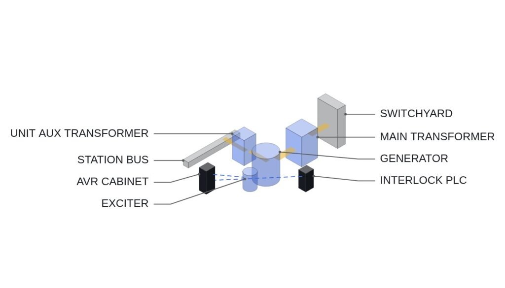
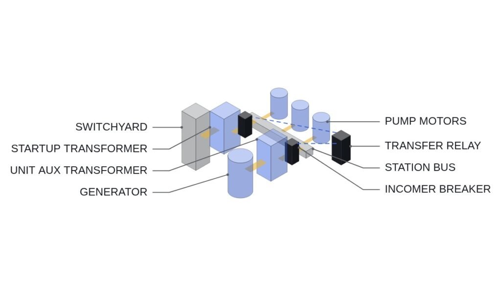
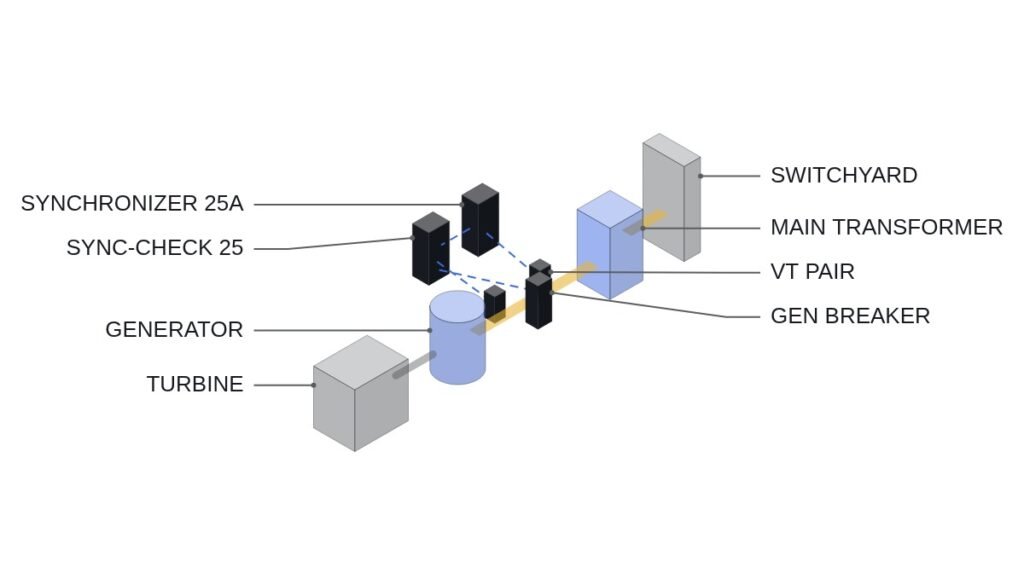
The short version: in PWR load-follow operation, whether a turbine load change request can be accepted is decided first not by ramp rate but by the margin left to the rod insertion limit and within the axial flux difference (ΔI) band. Reducing power is almost always possible. The trouble is ending up unable to raise it again because of the xenon transient that follows. So the logic that accepts turbine load requests should use “will there still be margin to return after the reduction?” as its interlock condition, not “can we reduce?”
Safety interlocks come first
Load-follow control happens in the control systems outside the reactor protection system. Its job is to filter requests before the plant gets anywhere near a protection actuation; it must not touch protection trip settings or actuation paths. Every interlock in this article is a request limit at the control system level.
- □ Reactor protection trips and ESFAS signals are read-only inputs to this logic and are never suppressed or delayed under any circumstances.
- □ Stop accepting turbine load reductions as the rod insertion limit (RIL) alarm is approached. The insertion limit protects shutdown margin, and load follow must not consume it.
- □ When ΔI approaches the edge of the operating band, hold both reduction and increase requests and hand the decision to the operator.
- □ If automatic rod control is unavailable (rod position indication mismatch, rod drive power fault), exit load-follow mode and switch to constant power operation.
- □ On loss of communication between turbine control and reactor control, converge to holding present power, not holding the last request.
- □ EMO circuits are hardwired; this logic only monitors their status.
Coordination schemes compared: which side moves first
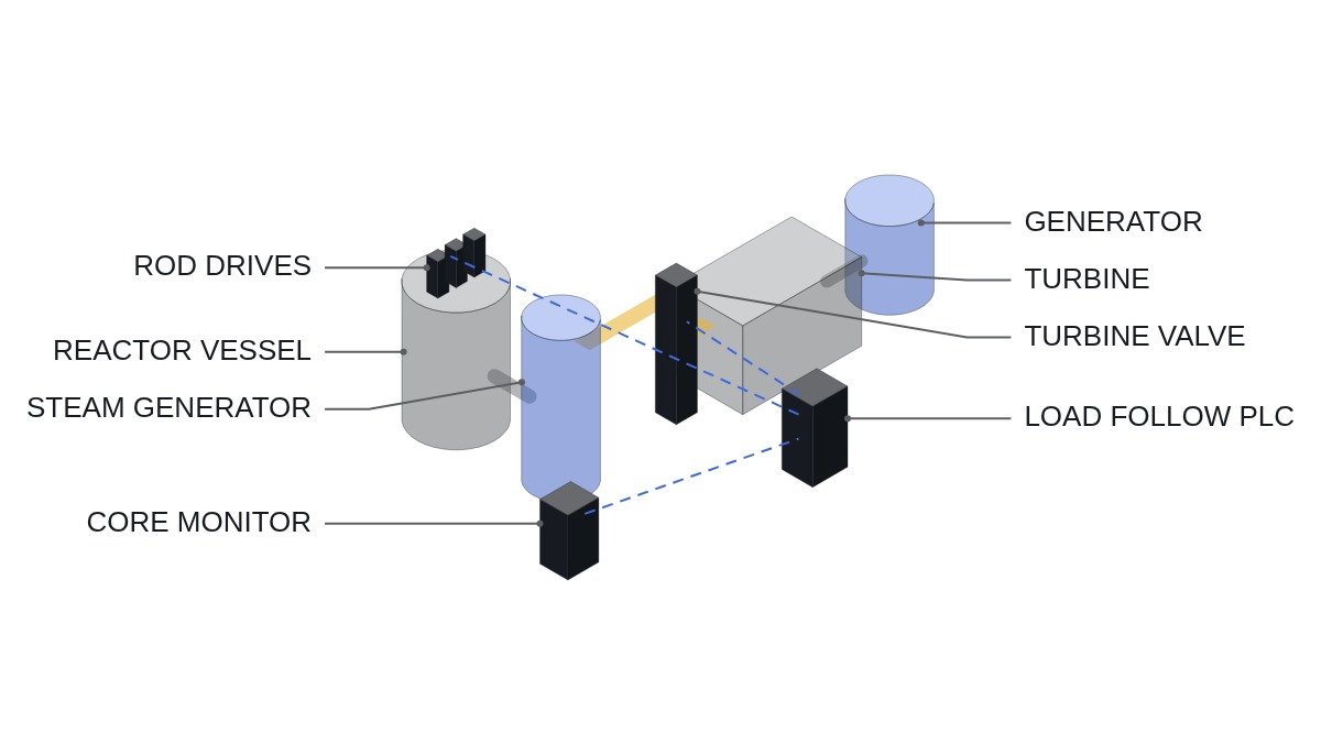
Load-follow coordination is classified by whether the turbine or the reactor moves first. In a PWR the turbine usually leads and the control rods follow changes in average coolant temperature (Tavg). The reverse, changing reactor power first and letting the turbine follow, also exists, and the two differ in response speed and in the size of the primary system transient.
| Scheme | Leading plant | Response | Primary burden |
|---|---|---|---|
| Turbine leading | Turbine governor | Fast | Large Tavg and pressurizer level transients |
| Reactor leading | Control rods | Slow | Small transients, delayed grid response |
| With boron | Chemical and volume control | Very slow | Restores rod position margin, generates liquid waste |
| With gray rods | Low-worth rods | Medium | Wider ΔI control margin (design-dependent) |
Read the table against the grid’s required rate. The faster the grid asks for changes, the more turbine leading makes sense, but it spends rod and ΔI margin just as fast, so the interlock conditions must be tighter. Boron adjustment is properly a means of bringing rod position back toward home to prepare for the next change; treat it as a fast-following tool and your judgment goes wrong.
Turbine load request acceptance flowchart
- Receive the request: target power and ramp rate from dispatch or the main control room.
- Mode check: automatic rod control available, load-follow mode selected, communication healthy.
- Margin check: at the target power, is predicted rod position above the insertion limit and ΔI inside the band?
- Return margin check: for a reduction, can rod and boron margin supply the reactivity needed to return to the original power after xenon builds up? The basis is taken as an input from core operation support calculations.
- Rate limit: ramp the turbine setpoint at or below the permitted rate.
- Reply: accepted, accepted at a reduced rate, or rejected, with the reason.
ST pseudocode: load-follow request interlock
(* I/O MAP - load-follow coordination PLC, control system separate from protection *)
(* %I4.0  DI_ROD_AUTO_AVAILABLE   : automatic rod control available *)
(* %I4.1  DI_LOAD_FOLLOW_MODE     : load-follow mode selected *)
(* %I4.2  DI_TURB_LINK_OK         : turbine control link healthy *)
(* %I4.3  DI_RIL_APPROACH_ALM     : rod insertion limit approach alarm *)
(* %I4.4  DI_RPS_TRIP_STATUS      : reactor trip status - monitoring only *)
(* %IW400 AI_DELTA_I_PCT          : axial flux difference, % *)
(* %IW401 AI_REACTOR_POWER_PCT    : reactor power, % *)
(* %IW402 AI_LOAD_TARGET_PCT      : requested target power, % *)
(* %IW403 AI_RETURN_MARGIN_PCM    : return reactivity margin - core calculation input *)
(* %QW400 AO_TURB_LOAD_SP_PCT     : turbine load setpoint, % *)
(* %Q4.0  DO_LF_REJECT            : request rejected reply *)
(* %Q4.1  DO_LF_MODE_EXIT         : exit load-follow mode *)

(* 1. No commands in trip state - no involvement in protection actions *)
IF DI_RPS_TRIP_STATUS THEN
    DO_LF_MODE_EXIT := TRUE;
    RETURN;
END_IF;

(* 2. Mode hold conditions *)
LF_OK := DI_ROD_AUTO_AVAILABLE AND DI_LOAD_FOLLOW_MODE AND DI_TURB_LINK_OK;
IF NOT LF_OK THEN
    DO_LF_MODE_EXIT := TRUE;
    TARGET := AI_REACTOR_POWER_PCT;      (* converge to present power *)
END_IF;

(* 3. Delta-I band margin - hold both directions near the edge *)
DELTA_I_BAND_OK := ABS(AI_DELTA_I_PCT - R_DELTA_I_TARGET) < (R_DELTA_I_BAND - R_DELTA_I_GUARD);

(* 4. Reduction request - check insertion limit and return margin *)
IF LF_OK AND (AI_LOAD_TARGET_PCT < AI_REACTOR_POWER_PCT) THEN
    IF DI_RIL_APPROACH_ALM OR NOT DELTA_I_BAND_OK
       OR (AI_RETURN_MARGIN_PCM < R_RETURN_MARGIN_MIN) THEN
        TARGET := AI_REACTOR_POWER_PCT;
        DO_LF_REJECT := TRUE;
    ELSE
        TARGET := MAX(AI_LOAD_TARGET_PCT, R_LF_MIN_POWER_PCT);
        DO_LF_REJECT := FALSE;
    END_IF;
END_IF;

(* 5. Increase request - check delta-I margin only, same rate limit *)
IF LF_OK AND (AI_LOAD_TARGET_PCT > AI_REACTOR_POWER_PCT) THEN
    IF DELTA_I_BAND_OK THEN
        TARGET := MIN(AI_LOAD_TARGET_PCT, 100.0);
        DO_LF_REJECT := FALSE;
    ELSE
        TARGET := AI_REACTOR_POWER_PCT;
        DO_LF_REJECT := TRUE;
    END_IF;
END_IF;

AO_TURB_LOAD_SP_PCT := RAMP_LIMIT(TARGET, R_LF_RATE_PCT_PER_MIN);
R_LF_MIN_POWER_PCT, R_LF_RATE_PCT_PER_MIN, the ΔI band and the return reactivity margin criterion all come from core design and the technical specifications, and this article gives no numbers for them. The return reactivity margin (AI_RETURN_MARGIN_PCM) is not something the PLC can compute on its own, so it is taken as an input from core monitoring calculations. If that input stops updating, the safe default is to reject reduction requests.
Pre-operation checklist
- □ Before entering load-follow mode, confirm control bank position is well above the insertion limit.
- □ Confirm ΔI is near target and, from recent power history, that the xenon distribution is steady.
- □ Confirm the boron adjustment plan (available dilution and boric acid injection) matches the day’s load pattern.
- □ Simulate loss of turbine-reactor control communication and confirm convergence to present power.
- □ Confirm reductions are rejected when the return margin input is stale.
- □ Record pressurizer level and pressure transients during power changes and assess control margin. The effect of instrument signal noise requires waveform analysis and field measurement.
Boundary conditions: when this design is wrong
First, end of core life. With boron concentration low late in the cycle, the reactivity available from boron dilution shrinks and the return margin falls quickly. With the same interlock settings as at beginning of cycle, reductions may be accepted and returns then blocked, so the return margin criterion should vary with cycle burnup.
Second, designs that use gray rods or mechanical shim operation. They depend less on boron and control ΔI by different means, so the interlock combination here may be overly conservative.
Third, load changes that are not a scheduled once-a-day pattern but continuous small swings such as frequency regulation. There, accumulated rod stepping and drive mechanism wear become the constraint before xenon does.
The single decision rule: accept a load reduction not on “can we go down now?” but on “after xenon builds up, will there still be enough reactivity margin to return to the original power?”