Bottom line first. When choosing a hydrogen supply path for a stationary fuel cell plant, green hydrogen always wins on carbon grade alone. But a stationary fuel cell is a continuous baseload asset, so the first question is supply continuity. On-site reforming (gray) has the best continuity but emits carbon on site. Blue hydrogen only works with capture at large central plants, so it drags a pipeline or transport leg behind it. Green hydrogen made from solar alone, on the assumptions below, demands an electrolyzer roughly ten times the fuel cell rating plus storage close to a day’s worth of consumption. The real selection criterion is: what carries the plant through continuous operation?
How the three paths differ in structure
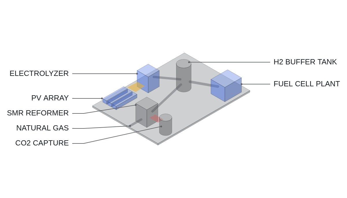
Gray hydrogen comes from steam reforming of natural gas with the CO2 vented to atmosphere. Where a PAFC or SOFC power package has a built-in reformer, the plant is fed natural gas and effectively makes and uses gray hydrogen on site. Blue hydrogen is the same reforming process with CO2 capture and storage (CCS) added, and green hydrogen is water electrolysis powered by renewable electricity.
The CO2 from reforming has a stoichiometric floor. In CH4 + 2H2O → CO2 + 4H2, four moles of hydrogen (about 8.06 g) come with one mole of CO2 (about 44.0 g), so process CO2 alone is about 5.5 kg per kg of hydrogen. If the heat for the reforming reaction is supplied by combustion, that share is added on top, so actual emissions are higher.
| Item | On-site reforming | Blue (central + CCS) | Green (electrolysis) |
|---|---|---|---|
| Carbon | Emitted on site | Depends on capture rate | Depends on power source |
| Supply continuity | Same as gas grid | Depends on transport | Depends on renewable output |
| H2 purity | CO / CO2 present | High after purification | High |
| On-site equipment | Built-in reformer | Storage, pressure letdown | Electrolyzer, storage |
| Capture feasibility | Hard at small scale | Works at large scale | Not applicable |
Read the table down each column and every path has one weak cell: carbon for on-site reforming, transport for blue, continuity for green. Given that a stationary fuel cell runs as continuous baseload, green hydrogen’s weakness has to be filled by storage, and the size of that storage decides the economics.
Where it wins, where it doesn’t
On-site reforming
Current condition: a site with a city gas connection and no hydrogen pipeline or transport infrastructure. After deployment: gas grid availability becomes fuel availability, so continuous operation is easy. Connecting logic: once carbon regulation or clean-hydrogen power auction conditions apply, on-site emissions count directly against the plant, and adding CO2 capture to a small distributed reformer does not reach economies of scale.
Blue hydrogen
Current condition: a supply hub with a large reformer linked to CO2 storage, and pipeline or tube-trailer delivery to the site. After deployment: carbon falls by the capture rate and purity rises. Connecting logic: fuel supply is tied to the delivery schedule, so on-site storage capacity sets how long a supply interruption can be tolerated.
Green hydrogen
Current condition: a site close to a renewable plant. After deployment: carbon falls sharply on a power-source basis, but hydrogen output swings with irradiance and wind. Connecting logic: attaching a variable supply to a continuous-duty plant means storage has to absorb the difference.
Worked assumption — 1 MW continuous operation on solar-only green hydrogen
Assumption: 1,000 kW fuel cell in continuous operation, 50% electrical efficiency (LHV), hydrogen LHV 33.3 kWh/kg, electrolyzer system consumption 55 kWh/kg, eight production hours per day for solar-coupled electrolysis. These are calculation assumptions, not equipment specifications.
| Item | Calculation | Result |
|---|---|---|
| H2 use per hour | 1,000 ÷ (33.3 × 0.5) | approx. 60 kg/h |
| H2 use per day | 60 × 24 | approx. 1,440 kg |
| Required production rate | 1,440 ÷ 8 | approx. 180 kg/h |
| Required electrolyzer power | 180 × 55 | approx. 9.9 MW |
| Night buffer (16 h) | 60 × 16 | approx. 960 kg |
Running a 1 MW fuel cell on solar-only green hydrogen takes an electrolyzer of about 10 MW and a storage buffer of two-thirds of a day’s consumption. Add runs of cloudy days and the buffer grows to several days. For the green path to be economic, that buffer has to be carried off site, by a pipeline network or a large storage hub.
How purity filters the paths
The supply path also interlocks with the fuel cell type. Reformate from on-site reforming carries CO and CO2 alongside hydrogen. PAFC runs at about 200 °C and tolerates more CO than low-temperature types, but still needs a CO shift stage after the reformer. SOFC can use CO as fuel and fits reformate best. PEM-based equipment, by contrast, is highly sensitive to CO and assumes high-purity hydrogen.
So the same site has a different set of viable supply paths once the fuel cell type changes. PAFC and SOFC plants moving from reforming to delivered hydrogen may need fuel-system modifications such as a reformer bypass, while PEM-based equipment only ever has high-purity supply paths on the list. If a fuel switch is planned, confirm the scope of that modification at equipment selection.
Decision sequence
- Fix the fuel cell operating pattern. Continuous baseload versus variable operation under dispatch commands is the starting point for choosing a supply path.
- Set the allowable fuel interruption time. This becomes the lower bound on on-site storage capacity.
- List continuity risks per path. Put gas grid availability, delivery schedule and renewable output variation in the same table.
- Confirm the hydrogen purity the fuel cell type requires. Whether it can take reformate or only high-purity hydrogen filters the paths.
- Apply carbon conditions (clean hydrogen certification grade, auction terms) last to narrow the remaining candidates.
Items to verify
- Emission grade bands of the clean hydrogen certification scheme and its accounting boundary (whether reforming combustion and indirect power emissions are included)
- Actual CO2 capture rate and storage route of the blue hydrogen supplier
- Electrolyzer system power consumption (kWh/kg) and part-load efficiency per product
- Allowable CO concentration and impurity limits per fuel cell type
Boundary conditions
Green hydrogen escapes its continuity weakness under certain conditions: when a hydrogen pipeline network reaches the site so that variation from many production points averages out inside the network, or when the renewable supply mixes wind and solar so production hours spread widely. On-site storage burden then falls sharply and the carbon advantage survives intact.
Conversely, on-site reforming keeps its advantage where carbon conditions are not tied to an auction or regulation and no hydrogen transport infrastructure exists; nothing else replaces gas grid continuity there. And if the fuel cell runs variably under dispatch commands, part of green hydrogen’s variation can be matched to the fuel cell’s running hours, which reduces the buffer needed. Whether shifting running hours is cheaper than a buffer depends on dispatch terms.
The single selection rule: among the paths whose continuous operation can be backed by off-site infrastructure (gas grid, hydrogen pipeline, storage hub), choose the shortest one that meets the carbon condition.