Here is the conclusion up front. Compressed air energy storage (CAES) and redox flow batteries are both long-duration technologies that let you scale power (kW) and energy (kWh) independently, but the vessel that holds the energy is fundamentally different. A flow battery stores energy in electrolyte tanks, a vessel you buy and fill. CAES stores it in something like a salt cavern, a vessel the geology provides. Flow battery electrolyte holds more energy per unit volume, yet on a site with a suitable underground cavity that volume comes almost free, so CAES pulls ahead as the scale grows. Without suitable geology, CAES drops out, and above-ground long-duration storage from a few MWh to several hundred MWh falls to flow batteries.
Where it wins, where it doesn’t
Where CAES wins
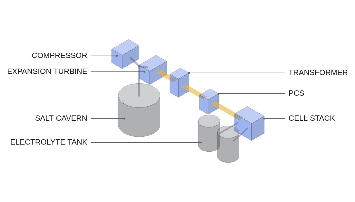
The current conditions: large, long-duration storage is needed, and beneath the site there is an airtight salt formation or a usable cavity. With CAES, surplus power compresses air into the cavern, and on discharge the air expands through a turbine-generator. Because storage is scaled by cavern volume, the marginal cost of adding energy is low, and because the output side is a synchronous generator, it contributes physical inertia to the grid. The connecting logic is the cost of the vessel: once geology supplies it, the kWh cost structure departs from anything electrochemical.
Where flow batteries win
The current conditions: an ordinary industrial or substation site with geological constraints, needing discharge of several hours or more and frequent cycling. With a flow battery, the cell stack sets power and the electrolyte tanks set energy, so duration grows simply by enlarging the tanks. Vanadium chemistries use the same element on both sides, so crossover through the membrane leaves room to recover capacity through rebalancing. The connecting logic is siting freedom and cycling durability.
Where both lose
Where discharge is around an hour and response speed comes first, both lose to lithium-ion ESS. Flow batteries have low power per unit volume because of their pumps and stacks, and CAES needs a mechanical start-up procedure.
Energy per unit volume
Put the two vessels on the same unit basis. All values are theoretical upper bounds; real usable energy is lower.
For compressed air, use the isothermal compression work: W = p × V × ln(p ÷ p0). Assumptions: storage pressure p = 7 MPa, ambient p0 = 0.1 MPa, volume V = 1 m³. W = 7,000,000 × 1 × ln(70) ≈ 7,000,000 × 4.248 ≈ 29.7 MJ, about 8.3 kWh/m³. A real cavern cannot be drawn below its minimum pressure, so only the operating pressure swing is usable.
For a vanadium flow battery, use Faraday’s law. Assumptions: vanadium concentration 1.6 mol/L, cell voltage 1.26 V, one-electron reaction, full SOC range used. One liter of electrolyte on one side holds 1.6 × 96,485 × 1.26 ≈ 194,500 J, about 54 Wh. Two tanks are needed, positive and negative, so on a total-electrolyte basis that is about 27 Wh/L, or 27 kWh/m³.
On the numbers alone, the flow battery is roughly three times better per unit volume. But a flow battery’s cubic meter is volume you must buy as tanks and electrolyte, while a CAES cubic meter already exists underground. The comparison is not energy density but the cost of obtaining that volume.
The calculation says one more thing. CAES energy per volume grows with the logarithm of pressure, so raising pressure pays off only slowly, while flow battery energy grows with concentration, which is capped by electrolyte solubility. Neither has much room to raise energy per volume, so the contest at scale is decided by the unit cost of the vessel.
Side-by-side comparison
| Item | CAES | Flow battery |
|---|---|---|
| Sets power | Compressor, expander | Cell stack |
| Sets energy | Cavern volume, pressure swing | Electrolyte tanks |
| Siting | Geology required | Above ground |
| Heat of compression | Fired reheat or heat storage | Not applicable |
| Fuel input | Gas for fired reheat | None |
| Grid inertia | Synchronous generator | Emulated by PCS |
| Auxiliary load | Cooling, lubrication | Electrolyte pumps |
The first row to check in this table is fuel input. A design that discards the heat of compression and burns natural gas to reheat the air on discharge is not pure electricity storage; it is closer to a gas turbine whose compression work has been prepaid with electricity. In that case, do not compare it with a flow battery on a single round-trip efficiency figure; list electricity input and gas consumption per output kWh separately.
Differences seen from operations
From the operator’s seat, the two behave differently on standby. While a flow battery’s electrolyte sits separated in the tanks, reaction is limited to the small volume inside the stack, so stored energy holds up relatively well through long idle periods. On restart, however, pump circulation and a stack state-of-charge check must come first, and if electrolyte temperature leaves its allowed range there is a precipitation risk, so HVAC and temperature interlocks must stay live at all times. In CAES, cavern pressure is the state of charge, so pressure measurement doubles as remaining-energy measurement, and start-up requires turbine warm-up and synchronization. Neither has zero standby auxiliary load, so in low-cycle duty this standby loss can upset the efficiency comparison. Actual standby power requires field measurement for each installation.
Decision sequence
- Use geological survey data to judge first whether a cavern is feasible at the candidate site. If the answer is no, the CAES review ends there.
- If CAES is feasible, fix the heat-of-compression approach. Fired reheat versus heat storage changes both carbon emissions and the definition of efficiency.
- Set the required discharge duration and annual cycle count. The more frequent the cycling, the more the flow battery’s aging behavior must be reflected in the evaluation.
- For flow batteries, get separate quotes for stack power and tank capacity, and compare on net efficiency including pump auxiliary load.
- If the grid requires inertia and short-circuit capacity, count the CAES synchronous generator’s contribution as a separate value.
Items to verify
- Cavern airtightness and allowable pressure swing (the operating pressure range sets usable energy)
- Actual electrolyte concentration, operating SOC range and supplier warranty terms for the flow battery
- Local permitting requirements for bunding and storage against electrolyte leaks
- Heat storage medium specification and discharge temperature for adiabatic CAES (to be confirmed per design)
Boundary conditions
The CAES advantage holds only on the premise that geology supplies the vessel. If the cavity must be excavated artificially or replaced with above-ground pressure vessels, the structure becomes buy-and-fill, CAES enters the same cost logic as a flow battery, and the option with more energy per volume wins. Designs that burn gas for reheat also lose ground as carbon regulation tightens. Conversely, the flow battery’s advantage fades as duration shortens and stack cost outweighs tank cost.
The single selection criterion: where geology provides an airtight cavern, choose CAES; on every other site, treat the flow battery as the default candidate for long-duration storage.