To state the conclusion first: choosing between string inverters and a central inverter does not end with an efficiency table or a cost-per-kW figure. Two questions decide it. How many kW does a single fault take offline, and do you want protection and interlocks concentrated on the DC side or on the AC side. For a multi-MW plant on flat, uniform ground with a single orientation and maintenance staff on site, the central inverter wins. Where orientations and tilts are mixed, shading is present, or a technician needs half a day or more to reach the site, string inverters win.
Safety interlocks: which layer carries what
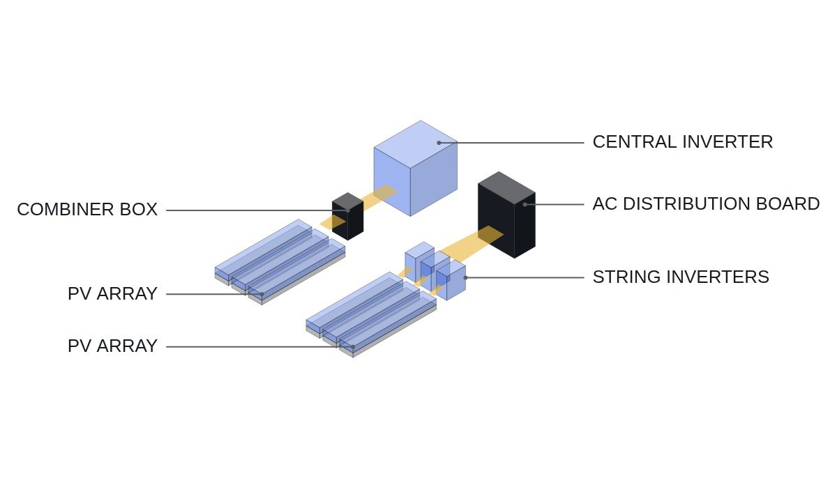
The two architectures put their interlocks in different places. A central inverter collects dozens of strings in combiner boxes and feeds the inverter through a DC bus carrying hundreds of amperes, so DC-side interruption and arc handling are the main risk. String inverters keep DC circuits short and currents small, but the number of AC-side parallel units grows, and protection coordination points and communication nodes grow linearly with it.
- □ Confirm that the emergency off (EMO) and fire-system tie-in open the switchgear breaker trip coil and the inverter external-stop terminals directly through hardwiring. The plant power controller (PPC) or PLC only monitors this path; it never resets or delays it in software.
- □ Central: confirm that the inverter gate block engages before the combiner output breaker (DC load-break switch) opens. Opening a DC switch under load current creates an arc.
- □ String: confirm a 1:1 ratio between AC distribution branch breakers and inverters, and that each branch breaker rating coordinates with the inverter’s maximum output current.
- □ Both: keep the point-of-connection protection relay trips (over/under-voltage, over/under-frequency) on a hardware path independent of each inverter’s internal protection.
- □ Both: define the inverter RUN PERMIT signal so that it converges to a predefined safe state when upstream communication is lost. Do not leave it at “hold last command.”
How many kW one fault takes offline
Two plants of equal capacity lose different amounts of energy when their fault isolation units differ. The values below are assumptions for the calculation. Assumptions: 3,000 kW plant, one central inverter versus thirty 100 kW string inverters, 15% capacity factor, and a 3-day repair time for both.
A central inverter fault costs 3,000 kW × 24 h × 0.15 × 3 days = 32,400 kWh. A single string inverter fault costs 100 kW × 24 h × 0.15 × 3 days = 1,080 kWh. With equal repair times, an isolation unit one-thirtieth the size means one-thirtieth the loss. The catch is that repair times are rarely equal.
| Item | Central inverter | String inverter |
|---|---|---|
| Fault isolation unit | One unit = most of the plant | One unit = a few to dozens of strings |
| DC-side risk | High-current DC bus, combiner arcs | Short DC runs, low current |
| AC-side risk | Single tie point, simple coordination | Many parallel units, many branch protections |
| MPPT granularity | One to a few per inverter | Several per inverter |
| Comm nodes | Few | Grows with inverter count |
| Repair method | On-site part swap, technician needed | Unit swap from spares stock |
| Installation | Dedicated room or packaged station | Distributed near the array |
What this table shows is not the total amount of risk but where it sits. A central inverter concentrates risk on the DC side while keeping AC-side logic simple; string inverters slice up the DC-side risk at the price of AC-side interlocks and an I/O map that scale with the inverter count. Which side your design team verifies more reliably effectively makes the choice.
Selection flowchart
- Check orientation, tilt, and shading. If two or more orientations are mixed, or morning and afternoon shading differ, go with string inverters that can split MPPT finely.
- Check technician response time and spares strategy. If response takes a day or more and you cannot keep a spare central power stack on site, go with string inverters.
- Check the interconnection voltage and room availability. If a step-up transformer is needed for medium-voltage interconnection and there is space for a packaged station, the central inverter has the layout advantage.
- Check the scope of AC-side protection coordination. Thirty string inverters in parallel means test items for thirty branch breakers and thirty communication nodes. Put that test time into the commissioning schedule.
- Check the DC-side arc and insulation monitoring method. For a central inverter, combiner-level monitoring is mandatory; for string inverters, confirm the operating conditions of the built-in functions from the manufacturer’s documentation.
Plant controller logic example
The pseudocode below shows a plant controller for a thirty-unit string inverter plant collecting per-inverter status and reporting available capacity upstream. For a central inverter the array size becomes one, and the combiner breaker status inputs increase instead.
(* IEC 61131-3 ST pseudocode - run permit and available capacity for 30 string inverters *)
(* %I0.0  DI_EMO_LOOP_HEALTHY     : EMO hardwired loop healthy (1) - monitoring only *)
(* %I0.1  DI_POC_RELAY_TRIP       : POC protection relay tripped (1) *)
(* %I0.2  DI_ACB_MAIN_CLOSED      : main breaker closed (1) *)
(* %IX10.0~%IX13.5 DI_INV_FAULT[1..30]    : per-inverter fault contact (1 = fault) *)
(* %IX20.0~%IX23.5 DI_BRK_BRANCH_CLOSED[1..30] : AC branch breaker closed (1) *)
(* %QX30.0~%QX33.5 DO_INV_RUN_PERMIT[1..30]    : per-inverter run permit *)
(* %MW200 PLANT_AVAIL_KW          : available capacity (kW) - reported upstream via MODBUS_TCP *)

VAR CONSTANT INV_RATED_KW : INT := 100; N_INV : INT := 30; END_VAR

PLANT_OK := DI_EMO_LOOP_HEALTHY AND NOT DI_POC_RELAY_TRIP AND DI_ACB_MAIN_CLOSED;
PLANT_AVAIL_KW := 0;

FOR I := 1 TO N_INV DO
    (* permit only when branch breaker closed + no fault + plant conditions met *)
    DO_INV_RUN_PERMIT[I] := PLANT_OK AND DI_BRK_BRANCH_CLOSED[I] AND NOT DI_INV_FAULT[I];
    IF DO_INV_RUN_PERMIT[I] THEN
        PLANT_AVAIL_KW := PLANT_AVAIL_KW + INV_RATED_KW;
    END_IF;
END_FOR;

(* upstream comm watch: no MODBUS_TCP response for 5000 ms raises comm alarm *)
TON_COMM(IN := NOT COMM_HEARTBEAT_OK, PT := T#5000MS);
COMM_LOSS_ALARM := TON_COMM.Q;   (* alarm only, does not affect run permit *)
The point of this logic is that available capacity is reported in unit steps. For a central inverter the value is either zero or full rating; for string inverters it drops in 100 kW steps. When the plant receives curtailment commands, that step size sets the response resolution. The 5,000 ms communication watch time is an example value; confirm the actual figure against the upstream system’s requirements.
Boundary conditions
The string inverter’s advantage rests on the premise that repair times are equal. If the central inverter manufacturer designed the power stack for module-level replacement and spare modules are kept on site so that repair takes a few hours, the difference in isolation unit no longer translates into a difference in lost energy. Conversely, even with string inverters, a batch defect that cascades across units from the same production lot erases the advantage of small isolation units.
AC-side noise and harmonics depend on the number of parallel units and the grid impedance, so no firm statement can be made; this requires waveform analysis and field measurement. In the end there is one criterion. Choose the architecture with the smaller expected lost kWh per fault (isolation unit kW × actual repair time).