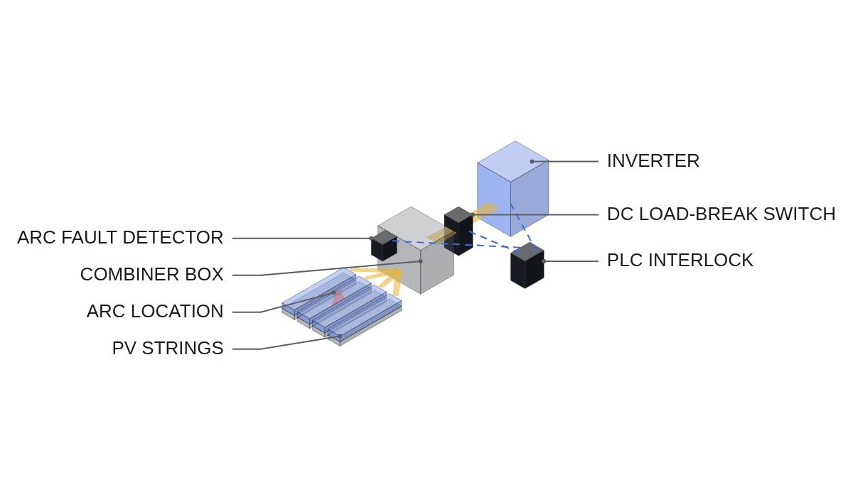
To state the conclusion first: the core of DC arc handling at the combiner box is not detection sensitivity but what gets opened, and in what order, after detection. A series arc goes out when the inverter stops drawing current, but a parallel arc between conductors or to ground keeps being fed as long as the PV modules see light. The interlock therefore has to run “inverter gate block → confirm current decay → open DC switch → isolate any string that still carries current,” and the current-decay check is the point at which a parallel arc reveals itself.
Safety interlocks: the opening sequence comes first
DC has no current zero crossing, so an arc is easily sustained when a switch interrupts load current. Before looking at arc detection logic, check the opening sequence and the switch ratings.
- □ Confirm that the emergency off (EMO) operates the inverter external-stop terminal and the combiner switch shunt-trip coil directly through hardwiring. The PLC receives the EMO loop state as a monitoring input only.
- □ Check the nameplate to confirm the combiner output switch has a DC load-break rating. A device rated only as a disconnector is operated only with no load.
- □ Interlock the switch opening command so it is issued only after the inverter gate block and after DC current has fallen below the set threshold.
- □ Confirm that string fuses or string disconnect means exist inside the combiner. They are the last means of isolating a string with a parallel arc.
- □ Block automatic restart after an arc trip, and confirm the restart condition (manual reset or not) against the applicable code edition and the inverter specification.
Different arcs need different interrupting means
What the field calls “arc detection” lumps together at least three phenomena. Whether stopping the inverter extinguishes the arc depends on where it originates.
| Type | Typical location | Out when inverter stops | Required means |
|---|---|---|---|
| Series arc | Loose connector, poor terminal, broken conductor | Mostly yes | Inverter gate block |
| Parallel arc | Insulation breakdown between + and – | No | Isolate the string, module-level shutdown |
| Ground arc | Between conductor and frame/earth | Possibly not | Ground-fault detection and string isolation |
The table says one thing. Stopping the inverter is only the first action and does nothing for parallel or ground arcs. That is why the interlock must include a step that measures whether current actually goes to zero after the inverter stops, and that measurement becomes the basis for classifying the arc.
Interruption flowchart
- Arc fault detector (AFD) trip signal received. Confirm detection time and energy criteria against the applicable standards (NEC 690.11, UL 1699B, IEC 63027) and the product certification conditions.
- Issue the inverter gate block command. Prioritize the hardwired signal through the inverter external-stop terminal; keep the communication command as backup.
- Monitor combiner output current. If current falls below the threshold within the set time, treat it as a series arc and open the output switch.
- If current persists past the set time, suspect a parallel or ground arc. In that case, rather than operating the output switch, check the per-string currents and identify strings whose current is reversed or non-zero.
- Isolate those strings and prohibit re-energization until field inspection. Until the plant stops generating at night, write work procedures on the assumption that the parallel arc path remains energized.
PLC logic example
(* IEC 61131-3 ST pseudocode - combiner DC arc interruption interlock *)
(* %I0.0   DI_EMO_LOOP_HEALTHY   : EMO hardwired loop healthy (1) - monitoring only *)
(* %I0.4   DI_AFD_ARC_DETECTED   : arc fault detector tripped (1) *)
(* %I0.5   DI_DCSW_CB01_OPEN     : combiner CB01 output switch open (1) *)
(* %IW100  AI_CB01_DC_CURRENT_A  : combiner output current (A, scale 0.1 A) *)
(* %IW110~%IW121 AI_STR_CURRENT_A[1..12] : per-string current (A) *)
(* %Q0.0   DO_INV_GATE_BLOCK     : inverter external-stop terminal output *)
(* %Q0.1   DO_DCSW_CB01_TRIP     : CB01 switch shunt-trip coil *)
(* %Q0.2   DO_ARC_ALARM          : arc alarm lamp and upstream report *)

VAR CONSTANT I_ZERO_A : REAL := 2.0; T_DECAY : TIME := T#300MS; END_VAR

IF DI_AFD_ARC_DETECTED THEN
    ARC_LATCH := TRUE;                  (* hold until manual reset *)
END_IF;

DO_INV_GATE_BLOCK := ARC_LATCH;         (* step 1: stop inverter current *)
DO_ARC_ALARM      := ARC_LATCH;

TON_DECAY(IN := ARC_LATCH, PT := T_DECAY);

(* step 2: open switch only after current decay - avoids load-break arc *)
IF ARC_LATCH AND (AI_CB01_DC_CURRENT_A < I_ZERO_A) THEN
    DO_DCSW_CB01_TRIP := TRUE;
    ARC_TYPE := 1;                      (* 1 = series arc presumed *)
ELSIF TON_DECAY.Q AND (AI_CB01_DC_CURRENT_A >= I_ZERO_A) THEN
    ARC_TYPE := 2;                      (* 2 = parallel/ground arc suspected, switch operation withheld *)
    FOR K := 1 TO 12 DO
        STR_SUSPECT[K] := (AI_STR_CURRENT_A[K] < -0.5) OR (AI_STR_CURRENT_A[K] > I_ZERO_A);
    END_FOR;                            (* flag strings with reverse or residual current *)
END_IF;

(* reset: manual push button %I0.7 DI_ARC_RESET_PB after field check, only when detector clear *)
IF DI_ARC_RESET_PB AND NOT DI_AFD_ARC_DETECTED AND DI_DCSW_CB01_OPEN THEN
    ARC_LATCH := FALSE; ARC_TYPE := 0;
END_IF;
The 2.0 A threshold and 300 ms decision time are examples. The actual current decay curve depends on the discharge behavior of the inverter DC-link capacitors and on the current sensor response, so record the current waveform after gate block during commissioning and set the values from it.
False trips and items to verify
Arc fault detectors judge by the high-frequency content of the current. Inverter switching components, resonance on long DC cable runs, and electromagnetic interference from neighboring equipment can look similar to an arc signature. If false trips recur, record irradiance changes and inverter operating state at the time of each event and look for correlation before lowering sensitivity. Pinning down the cause requires waveform analysis and field measurement.
Items to verify: detection time and energy criteria in the applicable code edition; restart requirements after an arc trip (manual or automatic); the DC load-break voltage and current ratings of the combiner switch; and whether the string current sensors can measure reverse current.
Boundary conditions
There are two cases where this sequence is wrong. First, in plants with module-level power electronics (MLPE), module output itself can be cut on arc detection, so even a parallel arc is extinguished at the source; there, confirming module-level shutdown comes before string isolation. Second, in layouts without a combiner where strings enter the inverter directly, the current-decay decision has to rely on the inverter’s internal measurement, which weakens the value of an external PLC interlock.
The criterion comes down to one sentence. If a current path can remain after the inverter stops, the interlock must name the means of breaking that path and the conditions under which that means may be operated.