Bottom line first. Whether to tie PV and ESS together with DC coupling or AC coupling is not decided by an efficiency figure. It comes down to two questions: does the ESS need to charge from the grid, and is it acceptable for PV and ESS to share a single inverter? For a new plant that has no need for grid charging and runs a high DC/AC ratio to recapture clipped energy, DC coupling wins. When you are adding storage to an existing PV plant, or you need grid charging, separate metering or independent maintenance, AC coupling wins. From an interlock standpoint, the first thing to recognize is that DC coupling creates a new fault path: the shared DC bus.
Start with the safety interlock conditions
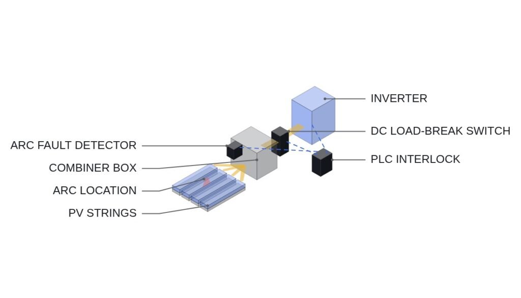
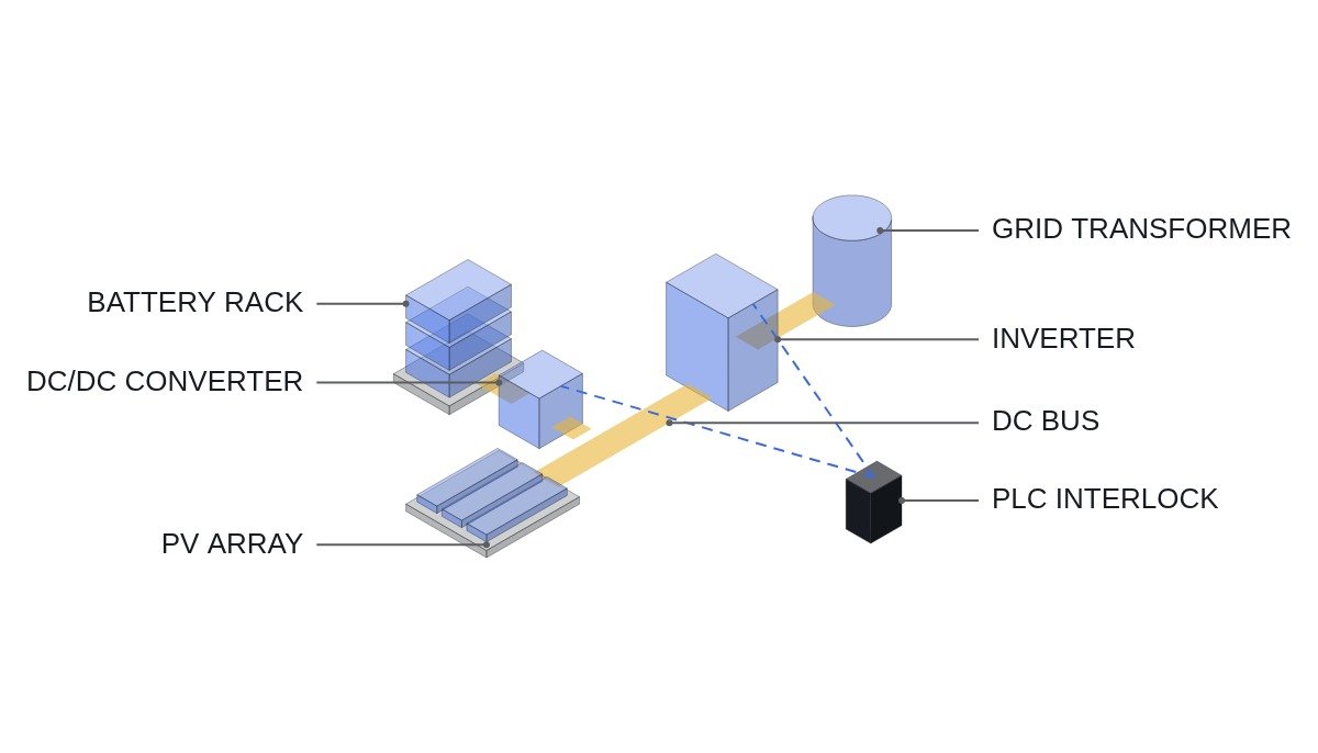
The two topologies have different protection boundaries. With AC coupling, the PV inverter and the ESS PCS each meet the grid at their own AC output, so the interlocks sit on each unit’s AC breaker and on the interface protection relay. With DC coupling, the PV array and the battery share one DC bus through a DC/DC converter, so the first job is to cut any path by which a DC fault on one side can carry over to the other.
- □ Confirm that EMO and fire detection open the inverter AC breaker, the battery rack contactor and the DC/DC converter input switch through hardwired circuits. The PLC only reads the status of this chain; it never bypasses or delays it in software.
- □ Define the sequence for a DC bus insulation monitor (IMD) alarm: stop the DC/DC converter first, then open the battery contactor. The PV array keeps producing voltage as long as there is irradiance, so disconnecting the battery side first reduces the number of fault energy sources to one.
- □ Make precharge completion (DC bus to battery voltage difference within the set window) an interlock before the battery contactor closes.
- □ Check PV string reverse-current paths. If any operating mode lets the battery side raise the DC bus voltage, re-check string fuse and diode ratings under that condition.
- □ For rooftop systems, confirm with the authority having jurisdiction whether the NEC 690.12 Rapid Shutdown requirement extends to the battery-side DC circuits.
Topology and the metering boundary
In DC coupling, the path is PV array, DC bus, inverter, grid, with the battery attached to the DC bus through a DC/DC converter. PV output above the inverter rating (the clipped portion) can be diverted into the battery ahead of the inverter, and in the evening the battery discharges through the same inverter. Fewer conversion stages is a side benefit. The bigger practical difference is that there is physically no path from the AC side into the battery. Unless the inverter is bidirectional, grid charging is structurally impossible.
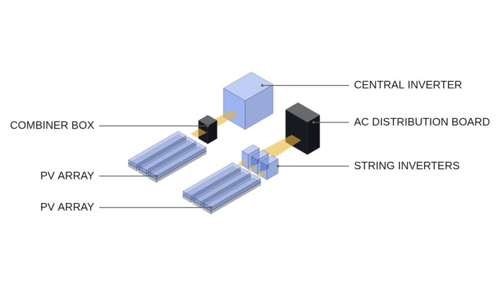
In AC coupling, the PV inverter and the ESS PCS each connect to the AC bus and reach the grid through a transformer. Because the PCS is bidirectional, grid charging is possible, and separating PV and ESS output onto different meters is straightforward. But where settlement rules require proof that the battery was charged only from PV, that condition has to be guaranteed by metering and control logic. What the physical topology guaranteed before now becomes the burden of a software interlock.
| Item | DC coupling | AC coupling |
|---|---|---|
| Clipping recapture | Yes (stored ahead of inverter) | No (lost behind inverter) |
| Grid charging | Only with bidirectional inverter | Yes |
| PV-only charging proof | Guaranteed by topology | Guaranteed by metering and logic |
| Single point of failure | Shared inverter | Distributed (per unit) |
| Retrofit to existing PV | Requires inverter replacement | Add a PCS |
| Interlock boundary | DC bus, DC/DC | AC breakers, PCC |
The rows that decide the question are the third and fourth. DC coupling satisfies the settlement condition by topology, but a single inverter trip takes down both PV and ESS. Inverter availability becomes plant availability, so spare inverter stock and repair time have to enter the design decision.
DC/DC converter run-permit logic
In DC coupling, the DC/DC converter is the center of the interlock. The pseudocode below summarizes the charge and discharge permit conditions. The preconditions are set against a timing chart as follows: battery contactor close command at t0, precharge completion confirmed after t0, and only then the DC/DC run permit. If an insulation alarm or an open safety chain is detected, the permit drops in the same scan.
(* I/O MAP - DC COUPLED PV+ESS *)
(* %I0.0  DI_SAFETY_CHAIN_OK    : EMO/FIRE HARDWIRED CHAIN STATUS (MONITOR ONLY) *)
(* %I0.1  DI_BAT_K1_CLOSED      : BATTERY MAIN CONTACTOR AUX *)
(* %I0.2  DI_IMD_ALARM          : DC BUS INSULATION MONITOR ALARM *)
(* %I0.3  DI_INV_AC_CB_CLOSED   : INVERTER AC BREAKER AUX *)
(* %IW100 AI_VDC_BUS            : DC BUS VOLTAGE (V) *)
(* %IW102 AI_VDC_BAT            : BATTERY VOLTAGE (V) *)
(* %IW104 AI_BAT_SOC            : SOC 0-100 % (BMS VIA MODBUS_TCP) *)
(* %IW106 AI_P_PV_AVAIL         : PV AVAILABLE POWER (kW) *)
(* %IW108 AI_P_INV_RATED        : INVERTER AC RATING (kW) *)
(* %Q0.0  DO_DCDC_RUN_PERMIT    : DC/DC CONVERTER RUN PERMIT *)
(* %Q0.1  DO_DCDC_CHG_MODE      : 1 = CHARGE FROM DC BUS, 0 = DISCHARGE *)

(* 1. PRECHARGE CHECK - VOLTAGE DIFFERENCE WITHIN WINDOW BEFORE PERMIT *)
B_PRECHARGE_OK := ABS(AI_VDC_BUS - AI_VDC_BAT) < R_PRECHG_DV;   (* EXAMPLE 20 V *)

(* 2. BASE PERMIT - HARDWIRED CHAIN, CONTACTOR, NO INSULATION ALARM *)
B_BASE_OK := DI_SAFETY_CHAIN_OK AND DI_BAT_K1_CLOSED
             AND NOT DI_IMD_ALARM AND B_PRECHARGE_OK;

(* 3. CHARGE ONLY WHILE PV EXCEEDS INVERTER RATING (CLIPPING RECAPTURE) *)
B_CLIP_CHG := (AI_P_PV_AVAIL > AI_P_INV_RATED) AND (AI_BAT_SOC < R_SOC_MAX);

(* 4. DISCHARGE ONLY WITH INVERTER CONNECTED TO GRID *)
B_DISCHG := DI_INV_AC_CB_CLOSED AND (AI_BAT_SOC > R_SOC_MIN)
            AND (AI_P_PV_AVAIL < AI_P_INV_RATED);

DO_DCDC_RUN_PERMIT := B_BASE_OK AND (B_CLIP_CHG OR B_DISCHG);
DO_DCDC_CHG_MODE   := B_CLIP_CHG;

(* 5. INSULATION ALARM - DROP PERMIT IN SAME SCAN; K1 OPENS VIA HARDWIRED PATH *)
IF DI_IMD_ALARM THEN
    DO_DCDC_RUN_PERMIT := FALSE;
END_IF;
R_PRECHG_DV, R_SOC_MAX and R_SOC_MIN are illustrative values. Actual values come from the battery maker’s BMS specification and the DC/DC converter’s input voltage range. The PV available power used in the clipping check has to be estimated while the inverter is no longer tracking the MPP, so confirm the estimation method against the inverter maker’s specification.
Field decision flow
- Check the settlement rules first. If ESS charging energy must come from PV to qualify for a weighting or tariff, the structural guarantee of DC coupling has real value.
- Check whether grid charging is needed. If the business case depends on arbitrage from low-price grid charging, narrow the choice to AC coupling or DC coupling with a bidirectional inverter.
- Calculate the DC/AC ratio and clipped energy. Assumption: with a 1,000 kW inverter and a 1,400 kWp array, there will be periods around clear-sky noon when PV exceeds the inverter rating. The recoverable amount has to be simulated with an annual irradiance profile and cannot be fixed in this article.
- Overlay the battery voltage range and the PV MPPT voltage range. The DC/DC converter’s input and output ranges must cover both.
- Evaluate the impact of the inverter as a single point of failure. Put spare inverter availability and replacement lead time into the availability calculation.
- Settle protection coordination. With DC coupling, review the interrupting capacity of DC breaking devices and fuses under the combined PV and battery short-circuit current.
Boundary conditions: when DC coupling loses
First, the moment grid charging enters the revenue model. A bidirectional inverter makes grid charging possible with DC coupling too, but at that point the advantage of guaranteeing PV-only charging by topology disappears, and you carry the same metering and logic proof burden as AC coupling.
Second, retrofits of existing PV plants. If the inverter already in service does not support a DC/DC connection, it has to be replaced, and the replacement cost and outage often cancel out the clipping recapture gain.
Third, the size of battery DC fault current. Battery short-circuit current is far larger than PV short-circuit current, so the ratings of protective devices on the shared DC bus go up. Actual fault current waveforms and interrupting times require waveform analysis and field measurement for each installation.
The single decision rule: choose DC coupling only when the ESS never needs to charge from the grid and you can accept one inverter trip taking down the whole plant; if either condition fails, choose AC coupling.