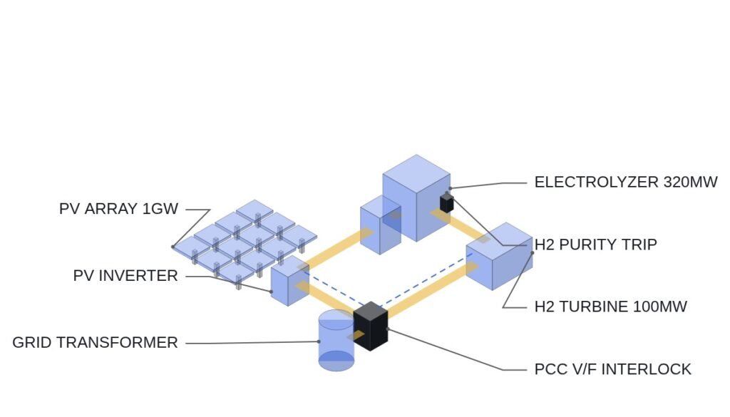
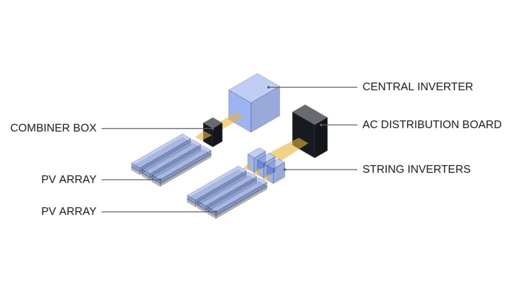
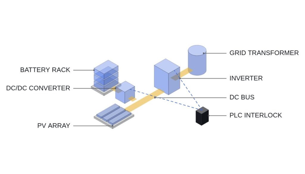
Bottom line first. Anti-islanding detection is adequately verified at the single-inverter level through a combination of passive and active methods, but once inverters from several manufacturers and an ESS share one point of interconnection, you should not trust inverter-level detection. Different active detection methods can partially cancel each other’s disturbances and lengthen detection time, and when an ESS PCS that holds voltage and frequency on its own is added, an island becomes indistinguishable from the normal grid from the PV inverters’ point of view. For such plants, make plant-level detection (interface relay plus transfer trip or an upstream breaker status signal) the primary path, and keep inverter-embedded detection as backup.
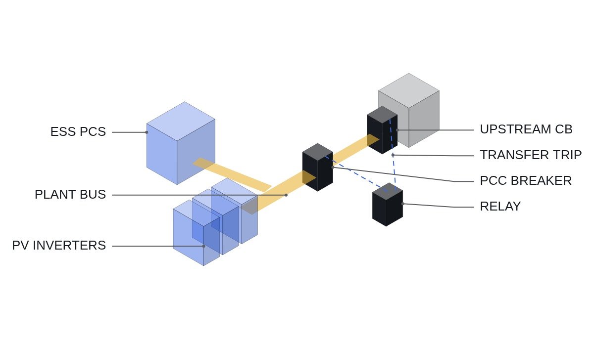
Safety interlock: islanding endangers people
The first reason islanding is dangerous is not equipment damage but worker safety. If the distribution operator opens a line and starts work while the plant keeps energizing it, a worker touches a line believed to be dead. The second reason is out-of-phase closing when the recloser operates.
- □ Wire the anti-islanding trip directly to the interface breaker trip coil. It must operate even if plant controller communication is lost.
- □ If Transfer Trip is used, monitor the communication channel and agree in advance with the distribution operator on the action taken on channel loss, whether limiting plant output or disconnecting.
- □ If the plant has a function in which the ESS feeds internal load after the interface breaker opens, put a hardwired interlock between the interface breaker and the switch to islanded operation. The PCS must not enter islanded (voltage-source) mode while the interface breaker is closed.
- □ EMO stops all inverters and PCS and opens the interface breaker through hardwired circuits; the detection logic uses EMO status as a monitoring input only.
- □ Permit reclosing of the interface breaker only after grid-side voltage has stayed within normal range for a defined time.
Where passive and active detection diverge
Passive detection watches for the change seen at the point of interconnection the instant the grid is lost: voltage or frequency excursion, voltage phase jump (Vector Shift), rate of change of frequency (ROCOF) and harmonic change are the typical signals. If plant output and on-site load differ significantly just before separation, voltage and frequency swing hard at the moment of separation and passive detection operates quickly.
The problem is when generation and load are nearly balanced. With a small power imbalance at separation, voltage and frequency barely change and passive detection sees nothing. This region is called the non-detection zone (NDZ). Active detection has the inverter inject a small disturbance into frequency or reactive power; with the grid present the grid absorbs it, and without the grid the disturbance grows, and that difference reveals the island.
The weakness of active detection appears when many units are combined. If inverter A pushes frequency upward and inverter B applies a disturbance in a different direction through reactive power, the two can weaken each other. The IEC 62116 procedure, which tests one inverter at a time, does not cover such combinations. And a grid-forming ESS PCS by definition tries to hold voltage and frequency, so inside the island it simply absorbs the PV inverters’ active disturbances. To a PV inverter, a grid-forming ESS looks like a small grid.
| Method | Principle | Weakness | Mixed plant |
|---|---|---|---|
| V/f excursion | Leaves setting range | Large NDZ | ESS holds range |
| Vector Shift | Phase jump | Misses small imbalance | Same |
| ROCOF | Frequency slope | Nuisance trips on grid events | ESS inertial response suppresses |
| Active frequency drift | Inject and amplify | Cancels across inverters | Absorbed by grid-forming |
| Transfer trip | Upstream breaker status | Depends on comms | Unaffected |
The last column is the basis for the decision. In a plant that includes a grid-forming ESS, every method that looks at electrical quantities at the point of interconnection weakens, and only transfer trip, which receives the upstream breaker status directly, is unaffected. When plant composition changes, the priority among detection methods has to change with it.
Plant-level anti-islanding logic
Assumed timing chart: at t0 the upstream substation breaker opens. The transfer trip signal arrives after the communication delay. Passive elements (ROCOF, Vector Shift) decide right after t0. Whichever condition is met first drives the interface breaker trip output. The code below is pseudocode explaining the logic of a dedicated relay, not a plant protection PLC, and the trip output leaves the relay contact over hardwiring.
(* I/O MAP - PLANT-LEVEL ANTI-ISLANDING LOGIC *)
(* %I5.0  DI_DTT_RECEIVED       : DIRECT TRANSFER TRIP FROM UTILITY SUBSTATION *)
(* %I5.1  DI_DTT_CHANNEL_OK     : DTT COMMUNICATION CHANNEL HEALTHY *)
(* %I5.2  DI_PCC_CB_CLOSED      : PCC INTERFACE CB CLOSED *)
(* %I5.3  DI_SAFETY_CHAIN_OK    : EMO CHAIN STATUS (MONITOR ONLY) *)
(* %IW700 AI_ROCOF_MHZ_S        : ROCOF AT PCC (mHz/s) *)
(* %IW702 AI_VEC_SHIFT_DEG10    : VECTOR SHIFT (deg x10) *)
(* %IW704 AI_P_PCC_KW           : ACTIVE POWER AT PCC (kW) *)
(* %Q5.0  DO_PCC_CB_TRIP        : TRIP TO PCC CB (HARDWIRED FROM RELAY CONTACT) *)
(* %Q5.1  DO_ESS_GFM_BLOCK      : BLOCK ESS GRID-FORMING MODE WHILE PCC CLOSED *)
(* %Q5.2  DO_P_LIMIT_REQ        : PLANT OUTPUT LIMIT REQUEST ON DTT CHANNEL LOSS *)

(* 1. PRIMARY - TRANSFER TRIP, NO DELAY *)
B_TRIP_DTT := DI_DTT_RECEIVED;

(* 2. BACKUP - PASSIVE ELEMENTS WITH SHORT CONFIRMATION TIMER *)
TON_ROCOF(IN := ABS(AI_ROCOF_MHZ_S) > I_ROCOF_SET, PT := T_ROCOF_CONFIRM);
B_TRIP_PASSIVE := TON_ROCOF.Q OR (ABS(AI_VEC_SHIFT_DEG10) > I_VS_SET);

(* 3. TRIP OUTPUT *)
DO_PCC_CB_TRIP := B_TRIP_DTT OR B_TRIP_PASSIVE;

(* 4. ESS MUST NOT FORM VOLTAGE WHILE CONNECTED UNLESS UTILITY ALLOWS IT *)
DO_ESS_GFM_BLOCK := DI_PCC_CB_CLOSED AND NOT B_UTILITY_GFM_ALLOWED;

(* 5. DTT CHANNEL LOSS - LIMIT OUTPUT SO THAT LOAD-GENERATION MISMATCH STAYS LARGE *)
(* SMALL NET EXPORT = LARGE NDZ RISK; AGREED ACTION WITH UTILITY *)
IF NOT DI_DTT_CHANNEL_OK THEN
    DO_P_LIMIT_REQ := TRUE;
END_IF;
I_ROCOF_SET, I_VS_SET and T_ROCOF_CONFIRM are example names. Setting ROCOF too low causes trips on normal grid disturbances such as the loss of a large generator, which conflicts with FRT requirements. Settings are chosen from the grid’s historical frequency disturbance records and the grid code, and whether nuisance trips occur on site requires waveform analysis and field measurement. The output limiting method in item 5 is a matter for agreement with the distribution operator.
Commissioning and operation checklist
- □ List the active detection method and manufacturer of every inverter and PCS connected at the point of interconnection. If the methods differ, consider whether a plant-level test is needed.
- □ If the ESS PCS supports grid-forming mode, find every condition under which that mode can become active while connected, and either block it with an interlock or obtain the distribution operator’s approval.
- □ Measure transfer trip channel latency at commissioning and record the margin against the disconnection deadline.
- □ Find the operating periods when net power at the point of interconnection is near zero (for example, noon at plants with heavy self-consumption) in the operating records, to quantify NDZ exposure time.
- □ Cross-check inverter-level test reports against IEC 62116, and interconnection requirements against IEEE 1547 or the applicable national grid code.
Boundary conditions: when inverter-level detection is enough
First, if the point of interconnection has only inverters of a single manufacturer and model, with no ESS or with an ESS that runs only in current-source (grid-following) mode, there is stronger ground for trusting the type test results of the embedded detection as they are.
Second, if plant output is always much larger or much smaller than on-site load, so that net power at the point of interconnection never sits near zero, NDZ exposure is small and passive detection alone operates quickly.
Third, in areas where the distribution operator does not provide a transfer trip channel, plant-level detection ultimately relies on electrical quantities at the point of interconnection too. There, blocking grid-forming mode and constraining output operation become the practical countermeasures.
The single decision rule: if a single point of interconnection has even one inverter with a different active detection method or one ESS capable of operating as a voltage source, move the primary anti-islanding path from the inverters to the plant level.