Bottom line first. Setting OVR, UVR, OFR and UFR at a renewable plant’s point of interconnection is not a question of how sensitively to trip. It is a question of finding the window between two curves. The lower boundary is the FRT (ride-through) curve required by the grid code. The upper boundary is the disconnection deadline for islanding and the dead time of the distribution line recloser. If the trip time is shorter than the FRT curve, the plant drops off needlessly on every grid fault; if it is longer than the reclose time, the recloser closes out of phase onto a line the plant is still energizing. And what actually narrows this window is often not the interface relay but the inverter’s internal protection settings.
Safety interlock: what to confirm before any setting
- □ Wire the interface protection relay’s trip output directly to the interface breaker trip coil. It does not pass through the PLC or the plant controller.
- □ When the relay self-check (WATCHDOG) contact opens, withdraw the close permit for the interface breaker. Never create a state in which the plant is connected to the grid without protection.
- □ Monitor the relay VT secondary circuit for fuse failure (VT Fuse Fail). Losing VT input makes UVR maloperate and OVR fail to operate, so the relay must have logic that blocks voltage elements and raises an alarm on VT failure.
- □ EMO and plant emergency stop stop the inverters and open the interface breaker through hardwired circuits, and must remain effective at all times regardless of any setting change work.
- □ Permit reclosing of the interface breaker only after grid voltage and frequency have stayed within normal range for a defined time (reconnection delay).
The setting window: lower and upper boundaries
The lower boundary is FRT. The grid code requires the plant not to disconnect for a defined time even when voltage drops to a certain level. If the UVR operating time falls inside that curve, the plant drops off whenever a distant line fault briefly depresses voltage. When a large block of renewables drops off at once, that itself becomes a grid frequency event, so the FRT curve is a mandatory lower limit on protection settings.
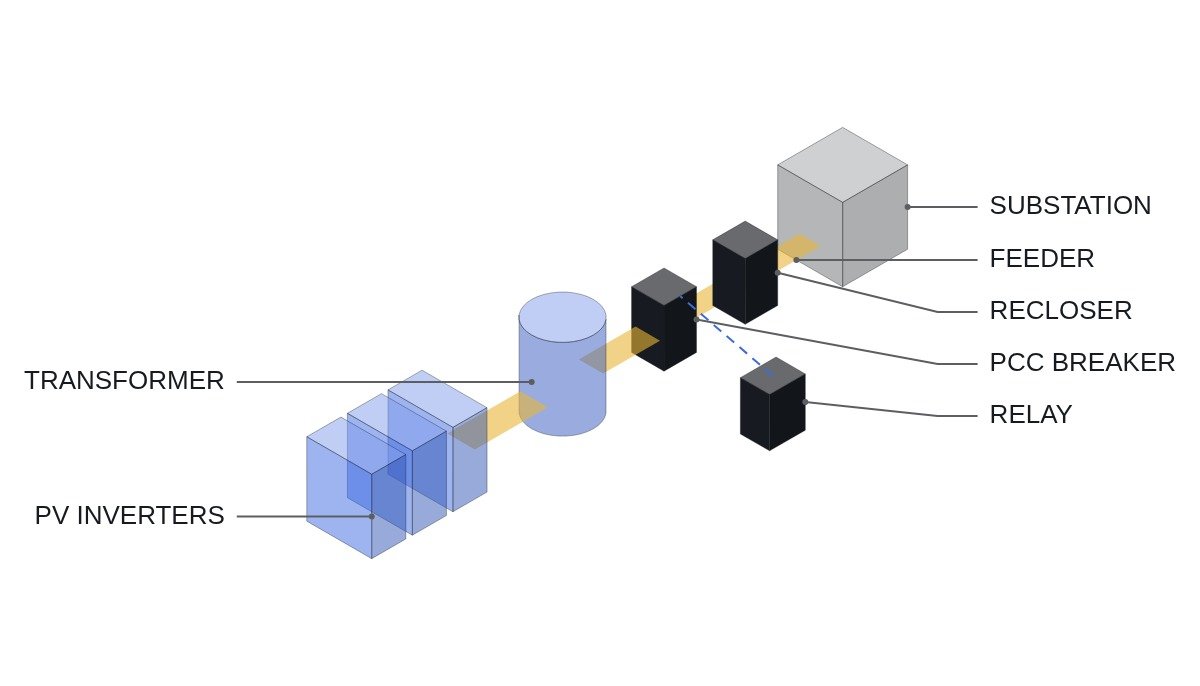
There are two upper boundaries. One is the islanding disconnection deadline. IEEE 1547 requires disconnection within 2 s of island formation; the deadline in the applicable national grid code has to be confirmed from the original text. The other is the distribution recloser dead time: the plant must be disconnected before the substation recloser closes again. The shorter of the two is the real upper limit.
The width of the window can be checked by calculation. Assumption: with recloser dead time T_RC, interface breaker opening time T_CB, relay measurement and decision delay T_M and margin T_MG, the maximum allowable operating time for voltage and frequency elements is T_RC − T_CB − T_M − T_MG. If this is shorter than the ride-through time FRT requires, the window is closed, and the answer is not a setting but a separate means such as Transfer Trip.
| Element | Protects against | Conflict with FRT | Check |
|---|---|---|---|
| UVR | Islanding, faults | Large (LVRT) | Time per stage |
| OVR | Islanding, overvoltage | Yes (HVRT) | Instantaneous element? |
| UFR | Islanding | Yes (frequency ride-through) | Order vs utility UFLS |
| OFR | Islanding | Yes | Order vs power curtailment |
| Inverter internal | The unit itself | Largest | Slower than relay? |
The last row is the part most often missed in the field. Even if the interface relay is set to respect FRT, an inverter whose internal protection is set shorter will drop off first, and the relay will not even record an operation. That is why root-cause analysis of a trip-off so often ends with the relay log. Also check the order for UFR: it must operate later than the grid’s under-frequency load shedding (UFLS) so as not to hinder frequency recovery.
Setting verification logic (plant controller supervision)
The code below does not perform protection. The relay performs protection; the plant controller reads relay and inverter settings over MODBUS_TCP, verifies they sit inside the window, and raises an alarm. Assumed timing chart: verification on the first scan after a setting change; on mismatch, withdraw the interface breaker reclose permit.
(* I/O MAP - SETTING WINDOW SUPERVISOR *)
(* %I4.0  DI_RELAY_WATCHDOG_OK : INTERFACE RELAY SELF-CHECK CONTACT *)
(* %I4.1  DI_VT_FUSE_OK        : VT SECONDARY FUSE MONITOR *)
(* %I4.2  DI_SAFETY_CHAIN_OK   : EMO / PLANT E-STOP CHAIN (MONITOR ONLY) *)
(* %MW600 AI_UVR_STAGE1_MS     : RELAY UVR STAGE 1 DELAY (ms), READ VIA MODBUS_TCP *)
(* %MW602 AI_INV_UV_TRIP_MS    : INVERTER INTERNAL UV TRIP DELAY (ms), READ VIA MODBUS_TCP *)
(* %MW604 AI_UFR_DELAY_MS      : RELAY UFR DELAY (ms) *)
(* %Q4.0  DO_CB_RECLOSE_PERMIT : INTERFACE CB RECLOSE PERMIT *)
(* %Q4.1  DO_SETTING_ALARM     : SETTING WINDOW VIOLATION ALARM *)

(* WINDOW LIMITS - FROM GRID CODE AND UTILITY RECLOSER DATA, EXAMPLE NAMES *)
(* I_FRT_HOLD_MS : MINIMUM RIDE-THROUGH TIME AT STAGE 1 VOLTAGE *)
(* I_RECLOSE_MS  : UTILITY RECLOSER DEAD TIME *)
(* I_CB_OPEN_MS, I_MEAS_MS, I_MARGIN_MS : BREAKER, MEASUREMENT, MARGIN *)

I_MAX_TRIP_MS := I_RECLOSE_MS - I_CB_OPEN_MS - I_MEAS_MS - I_MARGIN_MS;

(* 1. WINDOW OPEN? *)
B_WINDOW_OPEN := I_MAX_TRIP_MS > I_FRT_HOLD_MS;

(* 2. RELAY INSIDE WINDOW *)
B_UVR_OK := (AI_UVR_STAGE1_MS >= I_FRT_HOLD_MS) AND (AI_UVR_STAGE1_MS <= I_MAX_TRIP_MS);

(* 3. INVERTER MUST NOT BE FASTER THAN FRT, AND SHOULD BE SLOWER THAN RELAY *)
B_INV_OK := AI_INV_UV_TRIP_MS > AI_UVR_STAGE1_MS;

(* 4. UFR MUST BE SLOWER THAN LAST UFLS STAGE OF UTILITY *)
B_UFR_OK := AI_UFR_DELAY_MS > I_UFLS_LAST_MS;

DO_SETTING_ALARM := NOT (B_WINDOW_OPEN AND B_UVR_OK AND B_INV_OK AND B_UFR_OK);

DO_CB_RECLOSE_PERMIT := DI_RELAY_WATCHDOG_OK AND DI_VT_FUSE_OK
                        AND DI_SAFETY_CHAIN_OK AND NOT DO_SETTING_ALARM;
All variables are given names only. FRT ride-through time, recloser dead time and UFLS stage times have to come from the applicable grid code and the distribution operator’s equipment data; this article does not fix their values. If the inverter model does not allow its internal protection delays to be read remotely, obtain the settings table at commissioning and compare by hand.
Setting review sequence
- Transcribe the FRT curves (voltage-time and frequency-time) from the grid code into a table.
- Obtain the recloser dead time and number of reclose shots for the connection feeder from the distribution operator.
- Confirm interface breaker opening time and relay measurement delay from the specifications, and calculate the maximum allowable operating time with the formula above.
- If the window is open, place the relay’s per-stage times inside it. If it is closed, negotiate the introduction of transfer trip.
- Obtain the inverter’s internal protection settings and confirm they are slower than the relay. Change inverter settings only within the range the manufacturer approves.
- Check the difference in measurement location. The relay measures at the PCC (transformer HV side) and the inverter at its LV terminals, so the two voltages differ while reactive current is being injected. The actual difference requires waveform analysis and field measurement.
- Cross-check functional requirements against the IEC 60255 series, including IEC 60255-127 (over/under voltage protection) and IEC 60255-181 (frequency protection).
Boundary conditions: when window-finding does not work
First, if the feeder has no reclosing, or reclosing is preceded by a sync check, the upper boundary reduces to the islanding disconnection deadline alone. The window widens and FRT-first settings become easier.
Second, if the same feeder carries many other plants and ESS so that voltage and frequency can stay in normal range during an island, voltage and frequency elements cannot detect islanding. An open window means nothing here; transfer trip or active detection is needed.
Third, when the grid code is revised and FRT requirements tighten, existing settings get pushed out of the window all at once. The settings table is a document to be re-verified at every code revision.
The single decision rule: solve it with settings only when the recloser dead time minus breaker and measurement delays and margin is longer than the FRT ride-through time; if it is shorter, solve it with transfer trip, not settings.