To state the conclusion first: string insulation degradation should not be judged from a single reading but from the trend of the readings taken each morning just before the inverter starts. Insulation resistance is lowest at dawn because of condensation and humidity, and recovers by midday, so a string that passes a midday inspection can still block inverter start-up every morning. The ground-fault handling sequence splits into “stop immediately” and “alarm, then act within a deadline” depending on the array grounding (floating or functionally grounded) and the inverter type (isolated or non-isolated). If that branch is not settled first, correct logic will still produce wrong behavior.
Safety interlocks: settle the grounding scheme first
The same single-conductor ground fault drives different currents depending on how the array is grounded. Before writing interlock conditions, confirm the items below from drawings and nameplates.
- □ Confirm that the emergency off (EMO) opens the inverter external-stop terminal and the AC breaker through hardwiring. Ground-fault logic is separate from the EMO path; the PLC only monitors EMO status.
- □ Confirm whether the inverter is isolated (with transformer) or non-isolated. In a non-isolated inverter, the AC grid and the DC array are galvanically connected, so a ground fault immediately drives residual current.
- □ Confirm whether the array is floating or has one pole functionally grounded. A plant that grounds the negative pole as a PID countermeasure is a functionally grounded system.
- □ Confirm the settings of the inverter’s pre-start insulation resistance measurement and residual current monitoring from the manufacturer’s documentation. IEC 62109-2 is the standard that requires these functions; confirm the detailed thresholds against the applicable edition.
- □ Disconnect strings after a ground-fault alarm only with insulated gloves and a DC-rated meter, and only after confirming the string disconnect means is under no load.
Ground-fault handling by grounding scheme
| Configuration | Behavior on first fault | First action | Risk point |
|---|---|---|---|
| Non-isolated + floating array | Residual current flows | Immediate stop via residual current monitoring | Repeated nuisance trips |
| Isolated + floating array | Almost no fault current, operation can continue | Alarm, act within deadline | Second fault = short circuit |
| Isolated + functionally grounded array | Fault current flows through ground path | Ground-path interrupter operates | Array becomes floating after interruption |
The configuration most likely to be left unattended is the second row. Generation continues after the first fault, so the alarm gets pushed to “deal with it later,” and if a second fault occurs on the opposite pole in the meantime, it becomes a short circuit inside the array. For isolated inverters with floating arrays, the deadline for acting on the first ground-fault alarm must be written into the operating procedure as a number.
Reading the trend from morning readings
Before starting, the inverter measures the insulation resistance of the array’s positive and negative poles to ground, and it will not start if the value is below its setting. Pulling this value over communication and storing it by date gives early visibility of string degradation. The slope of a moving average is more useful than the absolute value. A single dip the day after rain recovers, but if the morning minimum keeps stepping down on clear days as well, suspect cable jacket damage or water ingress into connectors.
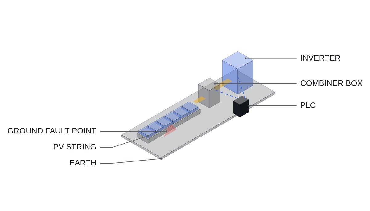
Location can be estimated from the voltage ratio. In a floating array, if the fault point sits n modules up from the negative pole, that point is at earth potential, so the negative-to-ground voltage is roughly n × module voltage and the positive-to-ground voltage is roughly (total modules − n) × module voltage. Assumption: 20 modules in series, 40 V operating voltage per module, negative-to-ground −240 V, positive-to-ground +560 V. Then 240 ÷ 40 = 6, so the area around the sixth module from the negative end is the candidate. This only holds when the fault resistance is low relative to the meter’s input resistance, so treat the result as a candidate section only.
Handling flowchart
- Receive the pre-start insulation reading from the inverter (MODBUS_TCP). If it is below the setting, confirm the start-inhibited state and mark that inverter as “insulation hold.”
- Request a re-measurement a set time after sunrise (e.g., 2 hours). If the value recovers, record it as condensation-related and keep it in trend data only.
- If it does not recover, disconnect strings one at a time at the combiner and measure each string’s voltage to ground.
- Estimate the candidate fault section from the voltage ratio and visually inspect the connectors and cable trays in that section.
- With that string disconnected, permit the remaining strings to restart. Tag the disconnected string “do not re-energize” until repair is complete.
PLC logic example
(* IEC 61131-3 ST pseudocode - insulation trend monitoring and ground-fault branch *)
(* %I0.0   DI_EMO_LOOP_HEALTHY     : EMO hardwired loop healthy (1) - monitoring only *)
(* %I1.0   DI_INV01_RCMU_TRIP      : inverter 01 residual current monitor trip (1) *)
(* %I1.1   DI_INV01_ISO_FAULT      : inverter 01 pre-start insulation fault (1) *)
(* %MW300  INV01_RISO_KOHM         : inverter 01 insulation reading (kOhm) - via MODBUS_TCP *)
(* %I1.2   DI_ARRAY_FLOATING       : array floating (1), functionally grounded (0) - config jumper *)
(* %I1.3   DI_INV_ISOLATED_TYPE    : isolated inverter (1) - config jumper *)
(* %Q1.0   DO_INV01_START_INHIBIT  : inverter 01 start inhibit *)
(* %Q1.1   DO_GF_ALARM_L1          : first ground-fault alarm (deadline timer starts) *)
(* %Q1.2   DO_GF_ALARM_L2          : deadline exceeded alarm *)

VAR CONSTANT R_TREND_DROP_PCT : REAL := 30.0; T_GF_DEADLINE : TIME := T#72H; END_VAR

(* 1. trend check: drop versus 7-day moving average of pre-start readings *)
IF MORNING_SAMPLE_READY THEN
    RISO_AVG7 := MOVING_AVG_7(INV01_RISO_KOHM);
    RISO_TREND_ALARM := (INV01_RISO_KOHM < RISO_AVG7 * (1.0 - R_TREND_DROP_PCT / 100.0));
END_IF;

(* 2. non-isolated: inverter stops itself on residual current, PLC only holds restart inhibit *)
IF NOT DI_INV_ISOLATED_TYPE AND DI_INV01_RCMU_TRIP THEN
    DO_INV01_START_INHIBIT := TRUE;
END_IF;

(* 3. isolated + floating: first fault is an alarm with a deadline timer *)
IF DI_INV_ISOLATED_TYPE AND DI_ARRAY_FLOATING AND DI_INV01_ISO_FAULT THEN
    DO_GF_ALARM_L1 := TRUE;
END_IF;
TON_GF(IN := DO_GF_ALARM_L1, PT := T_GF_DEADLINE);
DO_GF_ALARM_L2 := TON_GF.Q;              (* escalate upstream when deadline passes *)
IF DO_GF_ALARM_L2 THEN
    DO_INV01_START_INHIBIT := TRUE;       (* inhibit from next start, no forced stop while running *)
END_IF;
The 30% drop and 72-hour deadline are example values. Set the deadline in the operating procedure based on plant size and technician response time, and simply carry that value into the logic.
Boundary conditions
There are cases where trend judgment fails. If an inverter replacement or firmware update changes the measurement method, the new readings are not comparable with old data and the moving average must be reset. Also, a large array has many strings in parallel, so its combined insulation resistance reads low to begin with, and degradation in a single string may barely show in the total. In that case inverter-level measurement is not enough, and combiner-level insulation monitoring must be added.
Repeated residual-current nuisance trips caused by high-frequency leakage components or interaction between inverters have different causes at each plant; this requires waveform analysis and field measurement. The criterion is one sentence. If your configuration keeps generating after the first ground fault, put a deadline in both the logic and the procedure so that the fault is fixed before a second one can occur.