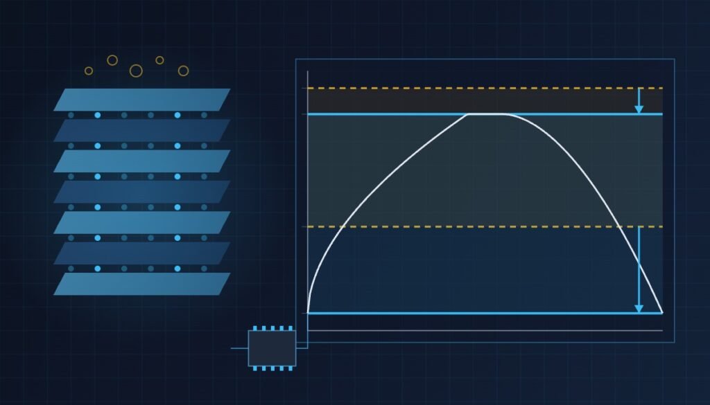
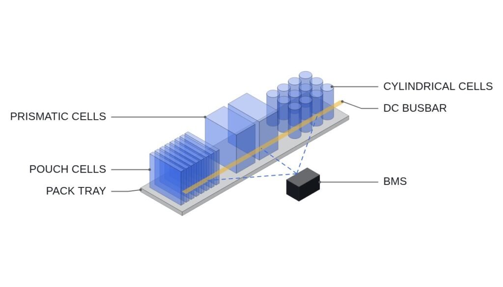
Bottom line first. CTP (Cell to Pack) and CTC (Cell to Chassis) remove module housings and the gaps between them so that cells take up a larger share of the pack. The gain comes in volume and part count; the price is that the unit of replacement, service and reuse grows from a module to a pack, and then to the vehicle body. CTP therefore wins in vehicles whose cell chemistry has low volumetric energy density that must be recovered through pack efficiency, and whose cell quality is consistent enough that cell-level replacement over the vehicle’s life is not assumed. Where cell replacement and second-life reuse must stay open, the module architecture still has the edge.
Where it wins, where it doesn’t
Current condition
In a module architecture, dozens of cells are grouped into a module, and each module carries end plates, side plates and a cell monitoring unit (CMU). The pack is the enclosure that holds the modules, and a fault is fixed by pulling and replacing a module. The module boundary is the assembly unit and the service unit, and it doubles as a physical compartment that interrupts thermal propagation between cells. The cost is that module enclosures and the spaces between modules fill a good part of the pack volume with structure rather than cells.
After the change
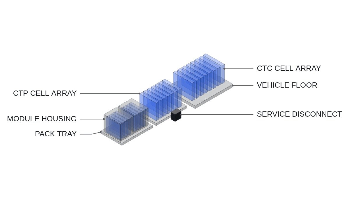
CTP removes the module enclosure and arranges cells directly in the pack housing. The cell volume fraction rises, and fasteners and assembly steps drop. CTC goes one step further and integrates the pack housing with the vehicle floor structure: the pack lid acts as the floor, or the body acts as the pack enclosure. The reference plane for the cell array becomes the pack or the body instead of the module.
Connecting logic
The more the structure is integrated, the better the volumetric efficiency, and the larger the unit you must remove when a single cell goes wrong. Module designs deal with one module, CTP with the whole pack, CTC with a structure bonded to the body. On the electrical side this shows up as follows. The number of cell voltage channels is set by the series count, so moving to CTP does not reduce it. What changes is the routing of sense wiring, the placement of CMUs, and where the service disconnect and high-voltage busbars go. The part count reduction happens in the mechanical design; the electrical design inherits a layout rework.
Architecture comparison
| Item | Module | CTP | CTC |
|---|---|---|---|
| Cell volume fraction | Low | High | High |
| Replacement unit | Module | Pack | Pack bonded to body |
| Thermal compartment | Module boundary doubles as one | Separate inter-cell barriers | Separate inter-cell barriers |
| Sense channels | Series count | Series count (same) | Series count (same) |
| Sense wiring | CMU daisy chain per module | Long runs inside pack | Routed along body structure |
| Second-life reuse | Easy module separation | Pack level, costly teardown | Separation itself is hard |
| Suited cell shape | Few constraints | Long prismatic, large cells | Long prismatic or cylindrical arrays |
The rows that decide the question are the replacement unit and second-life reuse. The volume gain is collected once, when the vehicle leaves the factory; the replacement-unit cost recurs every time a fault occurs over the vehicle’s life. Until you are confident that cell field failure rates are low, the replacement cost can outgrow the volume gain.
Chemistry and CTP fit
The volume gain from CTP is felt most with chemistries of low volumetric energy density. LFP cells, whose Wh/L is lower than NCM-family cells, tend to leave the pack short of energy in a module layout; removing module enclosures raises the cell volume fraction and closes part of that gap. LFP is also relatively thermally stable, so giving up the module boundary as a fire compartment carries a relatively smaller penalty.
By contrast, chemistries such as high-nickel NCM, which already have high cell energy density and release more energy in thermal runaway, require the pack design to provide separate thermal barriers and venting paths in place of the removed module boundaries. Part of the volume gain goes back into barriers and vent channels. That is why the effective gain from the same CTP concept varies by chemistry. The size of this difference depends on each cell and pack design and cannot be stated as a general number; judge it from thermal propagation test results.
What changes in the electrical layout
In a module pack, each module has a CMU, and CMUs connect through short communication links. Cell voltage sense wires terminate inside the module, so they are short, and replacing the CMU together with the module is natural. With CTP the module boundary is gone, so you must decide afresh where the sense wires and CMUs go inside the pack. Longer sense wires add wiring resistance and noise entry paths, and connector count and placement become reliability variables.
The high-voltage path also changes. Busbars that used to link modules now run long along the full cell array, and the service disconnect may move into the middle of the array. In CTC this device sits inside the body structure, so what a technician must dismantle before isolating high voltage becomes a design-stage check item. Insulation monitoring and the high-voltage interlock loop routing have to be redrawn for the same reason.
Decision sequence
- Confirm cell chemistry and cell shape first. Without long prismatic or large cells, a CTP array is hard to build at all.
- Check whether cell field failure-rate data exists. If not, add pack-level replacement cost to the lifetime cost and compare against a module design.
- Design a thermal barrier structure that meets thermal propagation requirements (market certification plus IEC and UL family pack tests) without module boundaries.
- Fix the sense wiring routes. Long sense wires become noise entry paths, so treat routing and filter design as items that require waveform analysis and field measurement.
- Confirm that the service disconnect position and the high-voltage isolation path are within service reach. In CTC, the key question is whether they can be reached without dismantling the body.
- If a second-life or recycling plan exists, estimate the teardown procedure and cost at the design stage.
The pivot of this sequence is step 2. Before cell field failure data accumulates, it is easy to treat the CTP volume gain as a certain gain and the replacement cost as an uncertain one. Only when both are placed in the same lifetime-cost frame does the architecture choice become an operating decision rather than a design preference.
Boundary conditions
The advantage of CTP and CTC reverses under these conditions. First, early in a cell’s supply life, before defect rates settle, pack-level replacement cost exceeds the volume gain. Second, when fleet or commercial vehicle contracts assume battery replacement or partial repair during vehicle life, module-level service lowers operating cost. Third, in business models that recover residual value by reusing packs as ESS, a structure that allows module-level separation largely determines reuse cost.
Fourth, in vehicles whose cells already have high enough energy density that pack volume is not the constraint, the core CTP gain shrinks. What remains is part count reduction, which has to be weighed against the larger replacement unit.
Fifth, thermal propagation measures can eat the volume gain. Replacing the fire-compartment role of module boundaries with barriers and vent channels brings non-cell volume back. If a high-energy chemistry needs thick barriers to pass thermal propagation tests, much of the cell volume fraction gained through CTP can be offset. The extent of that offset can only be confirmed by test.
The single selection rule: if pack volume is the range bottleneck and the vehicle does not assume cell or module replacement during life or module reuse afterwards, CTP wins; if even one of those must be assumed, the module architecture wins.