VOLTENERTEC WEEKLY · 2026 Week 37 · 2/4
Conclusion. Hyundai Motor and Kia have begun a 200kWh UBESS (Used Battery Energy Storage System) demonstration together with LG Energy Solution, Hyundai Engineering, and Wonik PnE. Unlike new cells, used battery packs are a collection of units with different histories. So the first interlock to set on this system is not an absolute threshold on cell voltage or temperature but a relative value: the spread in SOH and internal resistance between packs. The spread widens before any absolute threshold is reached.
1. Demonstration setup — what connects to what
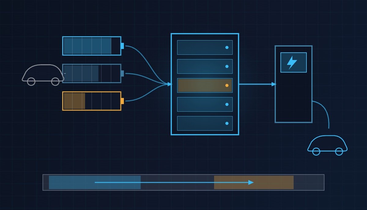
According to a report by the Electric Times (Jeonki Shinmun), five companies — Hyundai Motor, Kia, LG Energy Solution, Hyundai Engineering, and Wonik PnE — held a ceremony on September 10 at Wonik PnE’s Dongtan site in Hwaseong, Gyeonggi Province, to mark their cooperation on a UBESS demonstration based on used EV batteries. It is the first case in Korea to use used battery packs from electric vehicles on Hyundai Motor and Kia’s dedicated E-GMP EV platform, and the demonstration system totals 200kWh.
The operating scheme is simple. Electricity is stored in the UBESS during hours when electricity rates are low, and during high-rate hours it charges electric vehicles through a fast charger. In other words, the UBESS discharge path is tied directly to an EV fast charger rather than to the grid. From a control standpoint, this one line changes the design conditions considerably. For a grid-connected ESS, stopping discharge means a lost revenue opportunity, but in this configuration stopping discharge means an interruption of the charging service.
The participants said they will verify four items: the charge/discharge control algorithm, system safety and reliability, battery performance retention characteristics, and charging service quality and operating efficiency. The first two belong to protection design and the last two to availability design, and the point where these two collide is the core of the sequence below.
2. Check order — the safety interlock comes first
The order must not be reversed. However sophisticated the diagnostic logic is, if the hardwired safety interlock is not established first, there is no basis for closing the contactor. UBESS is no exception, and the check order is as follows.
- Hardwired safety circuit: the EMO (Emergency Off) chain, cubicle door limit switches, and gas detectors. This circuit must cut the main contactor coil circuit directly without passing through the PLC, and software only reads its status.
- Insulation resistance and grounding: recovered packs have been removed from vehicles and reassembled, so their insulation history differs from new units. Put the insulation resistance judgment as a separate step before closing.
- Absolute thresholds: maximum and minimum cell voltage, maximum temperature. Up to here, the items are the same as for a new-cell ESS.
- Relative spread: SOH spread and internal resistance (DCIR) spread between packs. This is the layer added in UBESS, and its result is first applied as output limiting (derating), not as a stop.
- Service ready signal: only after passing the four steps above is a service-available signal sent to the fast charger side.
3. What differs from a new-cell ESS
| Design item | New-cell ESS | Used-battery UBESS |
|---|---|---|
| Cell history | Same lot, similar cycle history | Driving and fast-charging history differs by vehicle |
| Primary judgment basis | Absolute voltage and temperature thresholds | Absolute thresholds + SOH and DCIR spread between packs |
| Allowable spread | Manufacturing tolerance level | Separate setting reflecting history differences |
| Action on abnormality | Stop charge/discharge | Derating first, stop at a higher grade |
| Consequence of a trip | Grid-side charge/discharge stops | Fast charging service stops at the same time |
| Maintenance decision | Interval-based inspection | Early replacement based on spread trend |
The row to act on first in practice is “Action on abnormality.” If the binary logic of a new-cell ESS (normal/stop) is carried over as is, one pack with a slightly wider spread can stop the entire fast charging service.
4. I/O map and charge/discharge permit sequence
Below is example logic that transcribes the check order above directly. The actual addresses and thresholds of the demonstration system have not been disclosed, so the addresses are notational examples and the thresholds show only where they are set.
| Address | Variable | Meaning |
|---|---|---|
| DI101 | DI_SAFETY_LOOP_HEALTHY | Hardwired safety circuit healthy (EMO, door, gas in series), TRUE = healthy |
| DI102 | DI_INSULATION_OK | Insulation resistance judgment relay contact |
| AI101 | AI_CELL_V_MAX | Highest cell voltage across all packs (V) |
| AI102 | AI_CELL_V_MIN | Lowest cell voltage across all packs (V) |
| AI103 | AI_CELL_TEMP_MAX | Highest cell temperature across all packs (℃) |
| AI104 | AI_SOH_SPREAD | Max-min SOH spread between packs (%) |
| AI105 | AI_DCIR_SPREAD | Internal resistance spread between packs (%) |
| DO101 | DO_MAIN_CONTACTOR_ENABLE | Main contactor close permit |
| DO102 | DO_CHARGER_SERVICE_READY | Fast charger service-available signal |
| AO101 | AO_DISCHARGE_POWER_LIMIT | Discharge power upper-limit command (kW) |
The point of the code below is that the spread judgment goes first into the output upper limit, and stopping is the next grade.
(* UBESS charge/discharge permit sequence - check order implemented step by step *)
(* STEP 1 : Hardwired safety circuit. The PLC only reads its status and never bypasses it *)
IF NOT DI_SAFETY_LOOP_HEALTHY THEN
    DO_MAIN_CONTACTOR_ENABLE := FALSE;   (* DO101 : cut immediately *)
    DO_CHARGER_SERVICE_READY := FALSE;   (* DO102 : report service unavailable *)
    RETURN;
END_IF;

(* STEP 2 : Insulation resistance judgment. Separate step for reassembled recovered packs *)
IF NOT DI_INSULATION_OK THEN            (* DI102 *)
    DO_MAIN_CONTACTOR_ENABLE := FALSE;
    RETURN;
END_IF;

(* STEP 3 : Absolute thresholds. Same protection grade as a new-cell ESS *)
IF (AI_CELL_V_MAX >= V_MAX_TRIP) OR (AI_CELL_V_MIN <= V_MIN_TRIP)
   OR (AI_CELL_TEMP_MAX >= TEMP_MAX_TRIP) THEN
    DO_MAIN_CONTACTOR_ENABLE := FALSE;   (* Protection grade : stop *)
    RETURN;
END_IF;

(* STEP 4 : Relative spread. UBESS-specific layer - applied first as output limit, not stop *)
IF (AI_SOH_SPREAD >= SOH_SPREAD_TRIP)
   OR (AI_DCIR_SPREAD >= DCIR_SPREAD_TRIP) THEN
    DO_MAIN_CONTACTOR_ENABLE := FALSE;   (* Spread has widened to stop grade *)
    RETURN;
ELSIF (AI_SOH_SPREAD >= SOH_SPREAD_DERATE)
   OR (AI_DCIR_SPREAD >= DCIR_SPREAD_DERATE) THEN
    AO_DISCHARGE_POWER_LIMIT := P_DERATED;  (* AO101 : maintenance grade - service continues *)
ELSE
    AO_DISCHARGE_POWER_LIMIT := P_RATED;
END_IF;

(* STEP 5 : Service signal only after passing the four steps above *)
DO_MAIN_CONTACTOR_ENABLE := TRUE;
DO_CHARGER_SERVICE_READY := TRUE;
5. Execution checklist
- Is each incoming pack’s unique identification code linked 1:1 in the equipment register to its vehicle history (mileage, number of fast charges)?
- Are the SOH and DCIR spread thresholds set as two separate values, a maintenance grade and a stop grade?
- When derating activates, is the signal sent to the fast charger distinguished as “limited output available” rather than “unavailable”?
- Have you confirmed on the drawings that the EMO, door, and gas detection circuits are wired to cut the main contactor coil circuit directly without passing through a PLC output?
- Is the insulation resistance judgment included as a step before contactor closing (and not replaced by monitoring after closing alone)?
- Is the spread data between packs recorded as a daily trend that can be used for early replacement decisions?
- When the charging window (light-load hours) changes, do the SOC target and the discharge upper limit reference the same schedule?
- Is the lower of the fast charger rating and the UBESS discharge upper limit sent out as the displayed service output?
6. Prior art — grade classification is an intake-time task
Reusing used batteries requires grade classification at intake first. The Korea Battery Research Association’s registered patent KR102289155B1 (filed 2021-02-09, registered 2021-08-11, Google Patents lookup result Expired – Fee Related) claims a process in which a grade classification server assigns unique identification codes to each incoming used battery pack and to each disassembled module, followed by pack information entry → electrical inspection → cleaning → visual inspection → disassembly into modules → module visual inspection → residual value assessment → grade classification. This patent is not held by the participants in this demonstration and is cited only as background art showing the general technical direction of used battery reuse processes.
What stands out is that this entire process is an intake-time task. The values secured through grade classification are a snapshot at the start of operation, and degradation that proceeds at a different rate in each pack afterward is not captured in the grade table. This is why the spread interlock in STEP 4 above is needed.
7. Boundary conditions — where this design reverses
- Scale: spread thresholds obtained from a single 200kWh site do not scale directly to large sites. As the number of packs increases, the tail of the spread distribution grows longer, and with the same threshold derating could be active all the time.
- Configuration dependence: the derating design is valid because the configuration is tied directly to a fast charger. If the UBESS is changed to a grid-connected configuration, the constraint of service interruption disappears, and simplifying the spread judgment to a stop grade is actually safer.
- Data gap: the actual protection parameters, cell chemistry, and PCS specifications of the demonstration system have not been disclosed. The threshold structure above is a proposal about design order, and specific values should be set after demonstration data is secured. Requires waveform analysis and field measurement.
In summary, the single decision criterion is this. When this system meets an abnormal signal, does the logic itself distinguish whether it is a signal to stop the service or a signal to lower the output? If it cannot, protection becomes excessive and availability collapses.
Source: Electric Times, September 10, 2026, “Hyundai Motor and Kia pursue UBESS demonstration with LG Energy Solution and Wonik PnE“. Patent bibliographic data and legal status from direct Google Patents lookup (2026-09-11).