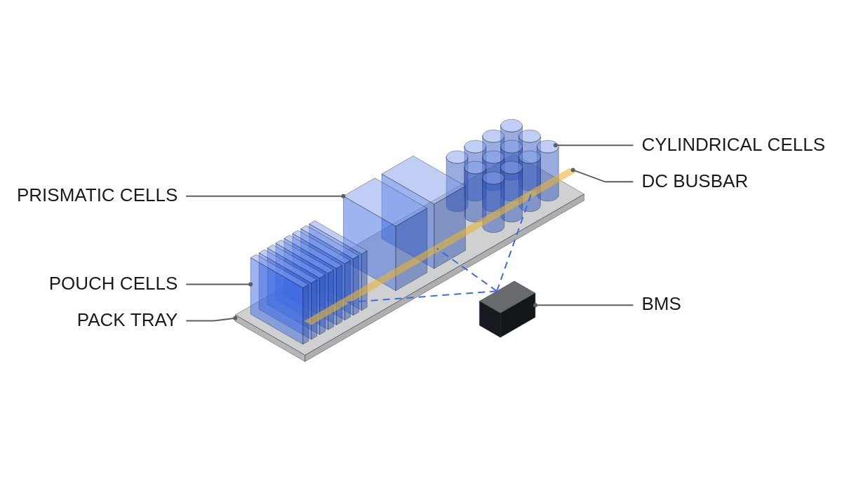
Bottom line first. In an EV battery pack, the choice between pouch, prismatic and cylindrical cells is not settled by cell-level energy density. It is settled by how many cells end up in parallel (P) once pack voltage and capacity are fixed, and by how much of the structural, swelling and thermal burden the pack has to carry because the cell does not carry it. Large prismatic cells keep P small and assembly simple, but a single cell failure can take down a whole series string. Small cylindrical cells push P high enough to absorb a single open-circuit failure, but the pack then owns the joint count and the cell fusing design. Pouch cells offer good volumetric efficiency but hand swelling restraint and mechanical protection entirely to the module and pack structure.
Where it wins, where it doesn’t
Current condition
Pack design usually starts from the cell datasheet. Engineers compare Wh/kg, Wh/L and continuous discharge current, pick a form factor, and only then work out the series-parallel configuration. In that order, questions such as how much structure the cell carries, or how a fault propagates inside a parallel group, get pushed to the end. The implicit assumption is that good numbers on a cell comparison sheet survive intact at pack level.
After the change
Work backwards from pack requirements and the answer shifts. Pack voltage sets the series count (S), and pack capacity divided by cell capacity sets the parallel count (P). Small cylindrical cells push P into the tens; large prismatic cells bring P down to one or two. Pouch cells, with a wide range of available sizes, can land anywhere in between. Once P is known, the joint count, the blast radius of a single cell failure, and the need for cell-level fusing all follow.
Connecting logic
One fact is often missed here. The number of BMS voltage-sensing channels is set by the series count (S) and does not depend on the parallel count. Cells in parallel share one voltage. A cylindrical pack with thousands of cells therefore needs the same number of voltage channels as a large-prismatic pack. What grows instead is the number of welds and joints, and the protection design inside each parallel group. Choosing a form factor is a choice about joint quality and fault isolation, not about monitoring electronics.
Pack burden by form factor
| Item | Pouch | Prismatic | Cylindrical (small) |
|---|---|---|---|
| Cell enclosure | Soft laminate, no structural role | Metal can, partial structural role | Metal can, high inherent stiffness |
| Swelling control | Module compression required | Can provides first restraint | Round section spreads internal pressure |
| Parallel count, same pack | Mid-range, size dependent | Small (about 1 to 2) | Large (tens) |
| Joint count | Medium (tab welds) | Low | High |
| One cell open-circuit | Group capacity drops | String may stop | Small group capacity drop |
| One cell internal short | Parallel cells feed current | Short feed path | Feed concentrates without cell fuses |
| Cooling contact | Wide flat face | Flat base and sides | Curved, small contact area |
Read the table column by column and each form factor shows what it hands to the pack. Pouch hands over structure and swelling, cylindrical hands over joining and parallel-group protection, and prismatic hands over fault isolation. None of them is burden-free; the burdens are simply different, and the practical call is to pick the one your pack team handles best.
Worked example: parallel count
Assumptions: nominal pack voltage about 400V, nominal cell voltage 3.6V, pack energy 80kWh. The series count is 400 / 3.6 ≈ 111, so we take 110S. Pack capacity is 80,000Wh / 400V = 200Ah. Changing only cell capacity gives the parallel counts below. The cell capacities are illustrative assumptions, not specific product ratings.
| Cell capacity (assumed) | Configuration | Total cells | Voltage channels |
|---|---|---|---|
| 5Ah | 110S40P | 4,400 | 110 |
| 50Ah | 110S4P | 440 | 110 |
| 100Ah | 110S2P | 220 | 110 |
| 200Ah | 110S1P | 110 | 110 |
Total cell count varies twentyfold, yet every configuration needs 110 voltage channels. If one cell fails open, a 40P group loses 1/40 of its capacity and keeps running, while a 1P configuration breaks the series string and stops the entire pack. Conversely, if one cell shorts internally, the other 39 cells in a 40P group push current into the fault, so per-cell fusing (wire-bond fuses and similar) becomes mandatory to cut that path.
Temperature sensing and parallel current sharing
Voltage channels follow the series count, but temperature sensing is a different matter. In a pack with thousands of cells you cannot put a sensor on every cell, so you measure at representative locations and estimate the rest with a thermal model. Packs with few large cells can realistically carry a sensor per cell, which shrinks the blind spots. Temperature sensing in a cylindrical pack is less about sensor count and more about finding locations that truly represent the hottest cell.
Current sharing inside a parallel group also behaves differently by form factor. Cells in parallel sit at the same voltage, but if joint resistance and busbar path length differ, current does not split evenly. Cells closest to the busbar entry can take more current and age faster. The larger P is, the more paths exist for this bias, so current sharing within a parallel group should not stop at design calculations; confirm it indirectly on prototypes through the per-cell temperature distribution.
Decision sequence
- Derive S and P from pack voltage and energy first. Choose the form factor after seeing the result.
- If P comes out at one or two, check whether a single cell open-circuit stops the pack, and whether the resulting vehicle behavior (power limit followed by a stop, for example) is acceptable.
- If P comes out in the tens, check the per-cell fuse structure and how joint quality will be inspected (100% resistance measurement or not) against process capability.
- If you choose pouch, confirm that the module and pack structure can hold the swelling restraint pressure to end of life, and what happens if that restraint relaxes.
- Match the cooling approach to the contact surface. Flat cold plates pair with pouch and prismatic; side contact on curved surfaces pairs with cylindrical.
- Re-verify crash safety and thermal propagation requirements (IEC and UL family pack tests, plus the target market’s certification) at pack level, regardless of form factor.
Boundary conditions
This reasoning flips under several conditions. First, as cylindrical cells grow in diameter and capacity, P drops and cylindrical packs inherit the same fault-isolation problem as prismatic ones. The deciding variable is capacity per cell, not the form factor name. Second, moving the pack to the 800V class nearly doubles S and halves P for the same energy. Parallel margin that was comfortable at 400V can disappear at 800V.
Third, when cell supply is locked to a single source, the comparison itself loses meaning. Once the available cell is fixed, the problem becomes finding the best S-P configuration for that cell, not choosing a form factor. Fourth, joint quality varies by process, so uneven current sharing within a parallel group can only be confirmed by measurement. Do not settle it on design calculations alone; keep it as an item that requires waveform analysis and field measurement.
Items to verify: cell swelling and the required restraint pressure. These values differ by cell design and chemistry and can only be confirmed from the cell maker’s data, so no general figures are given here.
The single selection rule: if the parallel count derived from your target pack voltage and energy is large enough to absorb a single cell failure, small cells (cylindrical or small pouch) win; if it comes out at one or two, large prismatic cells win only in applications that can tolerate a stop on failure.