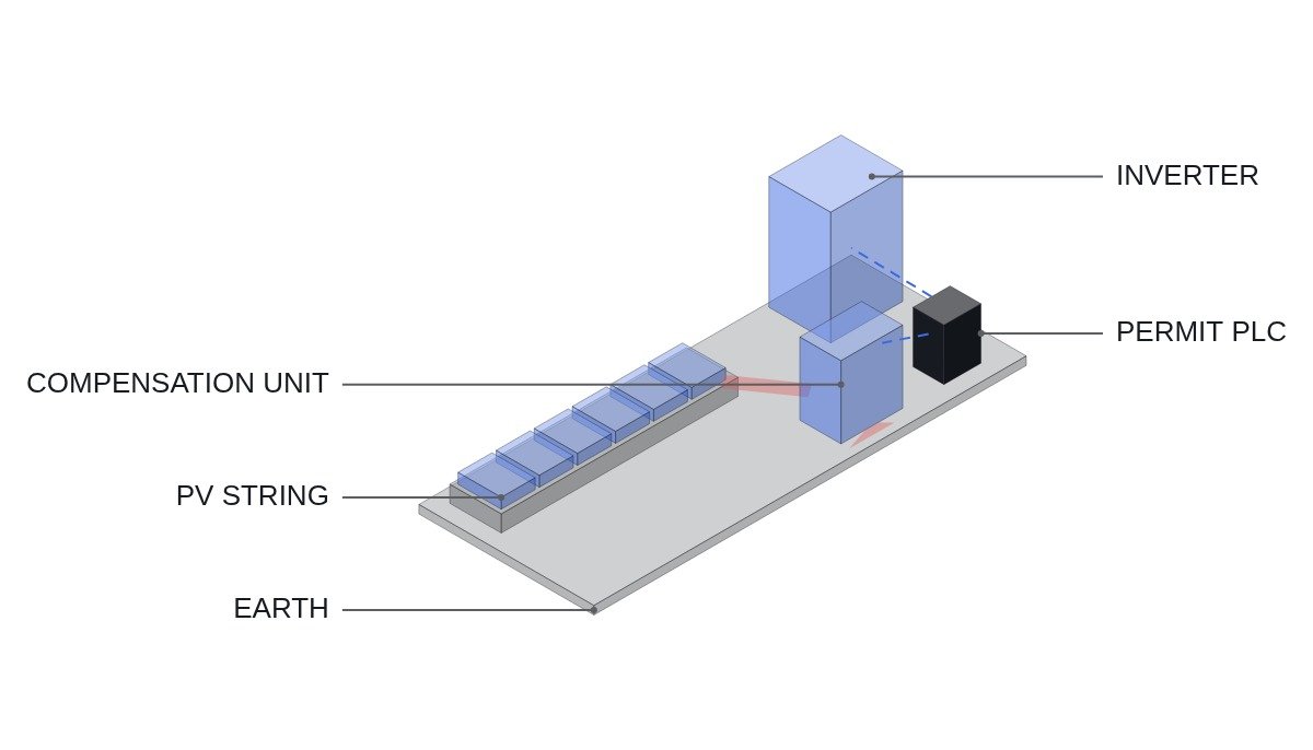
To state the conclusion first: a night-time potential compensation device for PID (potential-induced degradation) must not be run as a simple “on at night, off by day” timer. The device is a power source that applies a potential to ground on the array at night, turning it into a live part, so it has to be interlocked to operate mutually exclusively with inverter operation, insulation monitoring, and maintenance work. In particular, if the inverter’s pre-start insulation measurement runs at dawn while compensation voltage is still present, the measurement is corrupted; and applying compensation voltage to an array with a ground fault pushes current into the fault point.
Safety interlocks: treat the compensation device as a power source
PID is the loss of output caused by leakage current and ion migration when cells sit at a large negative potential relative to the grounded frame for long periods. In p-type crystalline modules it tends to appear first in modules near the negative end of the string, and it accelerates at high temperature and humidity. Night-time compensation reverses it by applying a potential of opposite polarity overnight. Because the device is a power source, confirm the following first.
- □ Confirm that the emergency off (EMO) opens the compensation device output contactor through hardwiring. A common wiring omission is to connect the EMO to the inverter and forget the compensation device. The PLC only monitors the EMO loop.
- □ Confirm that the compensation device output is physically disconnected while the inverter is connected on the AC side (running). Check the manufacturer’s pairing conditions to confirm it does not conflict with the inverter’s own insulation monitoring.
- □ Do not apply compensation voltage to an inverter circuit with an active insulation fault or ground-fault alarm.
- □ Confirm that combiner and inverter door switches and the maintenance mode selector block compensation output. The worker’s assumption that “night means de-energized” is wrong on this installation.
- □ Mark the site warning signs with “potential applied at night.”
Comparing PID countermeasures
| Method | Inverter condition | Effect on insulation monitoring | Watch point |
|---|---|---|---|
| Negative-pole functional grounding | Isolated inverter required | Array becomes a grounded system | Redesign ground-fault detection |
| Daytime potential offset | Inverter function or dedicated device | Array-to-ground potential shifts during operation | Confirm inverter pairing certification |
| Night-time reverse compensation | Only while inverter is stopped | Interference at the dawn transition | Live parts at night, transition order |
The three methods differ less in how they stop PID than in how much they disturb the existing protection scheme. Negative grounding is a one-time design change, but ground-fault detection has to be reconsidered from scratch; night-time compensation barely touches the existing design, but its two daily transitions have to be managed by interlock. For a retrofit, night-time compensation is the first candidate; for a new design, the grounding decision comes first.
Transition time chart and flowchart
Prerequisites differ from plant to plant, so the conditions are written against an operating time chart. Assumptions: the inverter starts and stops automatically on irradiance, and the compensation device outputs only on a PLC permit signal.
- Evening: confirm inverter AC breaker open (DI) → irradiance below setting for 30 minutes → confirm no insulation alarm → issue compensation permit.
- Night: monitor compensation output voltage and current. If leakage current exceeds the upper setting, withdraw the permit immediately and raise a suspected insulation fault alarm.
- Dawn: withdraw the permit at whichever comes first, irradiance reaching the setting or 30 minutes before the scheduled start time.
- After withdrawing the permit, grant the inverter start permit only once the compensation output contactor is confirmed open (DI) and the waiting time for the array-to-ground voltage to discharge has elapsed.
- Record the inverter’s pre-start insulation reading. If readings repeatedly drop on mornings after compensation runs, check the compensation device’s discharge path or the release sequence.
PLC logic example
(* IEC 61131-3 ST pseudocode - PID night-time compensation permit interlock *)
(* %I0.0   DI_EMO_LOOP_HEALTHY     : EMO hardwired loop healthy (1) - monitoring only *)
(* %I2.0   DI_INV_ACB_OPEN         : inverter AC breaker open (1) *)
(* %I2.1   DI_PIDB_CONTACTOR_OPEN  : compensation output contactor open (1) *)
(* %I2.2   DI_DOOR_OR_MAINT_MODE   : combiner/inverter door open or maintenance mode (1) *)
(* %I2.3   DI_INV_ISO_FAULT        : inverter insulation fault alarm (1) *)
(* %IW200  AI_IRRADIANCE_WM2       : horizontal irradiance (W/m2) *)
(* %IW202  AI_PIDB_LEAK_MA         : compensation leakage current (mA) *)
(* %Q2.0   DO_PIDB_ENABLE          : compensation output permit *)
(* %Q2.1   DO_INV_START_PERMIT     : inverter start permit *)

VAR CONSTANT G_NIGHT : INT := 5; I_LEAK_MAX : INT := 50; END_VAR

NIGHT_COND := (AI_IRRADIANCE_WM2 < G_NIGHT);
TON_NIGHT(IN := NIGHT_COND AND DI_INV_ACB_OPEN, PT := T#30M);

PIDB_OK := DI_EMO_LOOP_HEALTHY AND DI_INV_ACB_OPEN AND NOT DI_DOOR_OR_MAINT_MODE
           AND NOT DI_INV_ISO_FAULT AND NOT LEAK_LATCH;

(* latch on leakage above limit, clear after manual check *)
IF DO_PIDB_ENABLE AND (AI_PIDB_LEAK_MA > I_LEAK_MAX) THEN
    LEAK_LATCH := TRUE;
END_IF;

(* dawn release: irradiance rise or 30 min before scheduled start (DAWN_PRESTART is a clock-based flag) *)
DO_PIDB_ENABLE := PIDB_OK AND TON_NIGHT.Q AND NOT DAWN_PRESTART;

(* inverter start only after contactor confirmed open + 10 min discharge wait *)
TON_DISCH(IN := DI_PIDB_CONTACTOR_OPEN AND NOT DO_PIDB_ENABLE, PT := T#10M);
DO_INV_START_PERMIT := DI_EMO_LOOP_HEALTHY AND TON_DISCH.Q AND NOT DI_DOOR_OR_MAINT_MODE;
The 5 W/m2 irradiance threshold, 50 mA leakage limit, and 10-minute discharge wait are all example values. The discharge wait depends on the compensation output stage and the array’s capacitance to ground, so measure how long the array-to-ground voltage takes to fall after release during commissioning and set the value with margin.
Boundary conditions
There are cases where this design does not fit. N-type and thin-film modules may show PID under different polarity conditions from p-type modules, so check the module manufacturer’s recommendation for compensation polarity and voltage first. Applying the wrong polarity accelerates degradation instead of reversing it. Also, adding night-time compensation to a plant already designed with negative-pole functional grounding either cancels one countermeasure with the other or drives current through the ground path, so do not combine them.
Whether leakage-current fluctuations during compensation reflect humidity or insulation degradation differs from plant to plant; this requires waveform analysis and field measurement. The criterion is one sentence. Write the compensation permit not as “is it night?” but as “do the inverter, maintenance, and insulation states all allow the potential to be applied?”