Bottom line first. Choosing between lead-acid or lithium batteries and supercapacitors for the emergency supply of a wind turbine pitch system is decided less by lifetime cost than by how you prove, during operation, that emergency feathering can actually be completed. Both technologies have a degradation mode in which standby voltage looks normal but voltage collapses the moment load is applied. An interlock built on voltage monitoring alone is therefore not an interlock. You need periodic load tests that measure internal resistance and usable energy, and a structure that grants start permission only while the test history is valid.
Safety interlock: principles of the emergency pitch path
Emergency pitch feathering is the turbine’s last aerodynamic braking means. Whether the cause is grid loss, main controller failure, overspeed or emergency stop, the blades must turn to the feather position and bring the rotor to rest, and that path must not depend on the upper-level controller’s judgment.
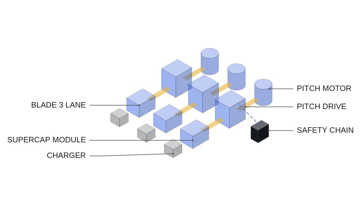
- □ The emergency feather command must originate from the opening of the hardwired safety chain. When the chain opens, each blade’s pitch drive starts running toward feather on its own emergency supply. The PLC is not the party that commands this action; it monitors the result.
- □ The emergency supplies of the three blades must be independent of each other. If one shared supply feeds all three blades, a single failure loses them all.
- □ Cross-check the feather limit switch (%I input) against the encoder angle on every operating cycle.
- □ Treat a backup charger fault alarm as grounds to withdraw start permission, not as an immediate stop. A running machine can still feather with the energy currently stored.
- □ Confirm that the pitch motor brake release supply is included in the emergency supply path. If the brake does not release, the blade will not turn no matter how much energy is available.
How batteries and supercapacitors fail differently
A battery sitting on float charge for long periods keeps its terminal voltage while capacity and internal resistance slowly deteriorate. Temperature swings inside the nacelle are large, and at low temperature usable capacity drops and internal resistance rises. That combination makes the battery weakest exactly when emergency feathering is most needed, such as a high-wind stop in winter.
With supercapacitors, stored energy is proportional to the square of voltage, so it is tempting to think that knowing the voltage means knowing the energy. Degradation, however, shows up as falling capacitance and rising equivalent series resistance (ESR). Lower capacitance means less energy at the same voltage, and higher ESR means a larger voltage drop the instant the pitch motor’s starting current flows, so the drive hits its undervoltage cutoff first. Standby voltage reveals neither form of degradation.
Usable energy can be checked by calculation. Assumption: a module with capacitance C = 10 F usable from a maximum voltage V1 = 60 V down to the drive’s minimum operating voltage V2 = 30 V. Usable energy is 1/2 × C × (V1² − V2²) = 0.5 × 10 × (3,600 − 900) = 13,500 J. If capacitance falls by 20%, the same calculation gives 10,800 J. The energy one feathering run needs is set by blade inertia, aerodynamic moment and pitch rate, and has to be obtained from the manufacturer for each model.
| Item | Battery | Supercapacitor |
|---|---|---|
| Main degradation metric | Capacity, internal resistance | Capacitance, ESR |
| Standby voltage reliability | Low | Low |
| Low-temperature effect | Large capacity loss | ESR rise |
| Energy estimate | Needs discharge curve | Calculated from V and C |
| Load test criterion | Voltage drop, duration | Instant drop, dV/dt |
| Replacement decision | Test result trend | Test result trend |
What the two columns share is the conclusion. Whichever you choose, standby voltage is not a valid criterion; the voltage drop and discharge slope from a load test are the only valid criteria. The supercapacitor’s advantage is that the evaluation is simple: the instant drop gives ESR, and the discharge slope dV/dt together with the current gives capacitance directly.
Load-test-based start permit logic
The assumed timing chart: blades are tested one at a time while idling in low wind. At t0 the charger is disconnected and the pitch motor is driven briefly at a defined current from the emergency supply alone. At t0 plus a few ms the instant drop is measured (ESR), and over the following interval dV/dt is measured (capacitance). The charger is reconnected after the test. While one blade is under test, the other two hold the feather position.
(* I/O MAP - PITCH BACKUP TEST, BLADE n = 1..3 *)
(* %I2.0  DI_SAFETY_CHAIN_OK     : HARDWIRED CHAIN STATUS (MONITOR ONLY) *)
(* %I2.1  DI_BLADE1_FEATHER_LS   : BLADE 1 FEATHER LIMIT SWITCH *)
(* %I2.4  DI_CHARGER1_FAULT      : BLADE 1 BACKUP CHARGER FAULT *)
(* %IW400 AI_UCAP1_V             : BLADE 1 BACKUP VOLTAGE (V x10) *)
(* %IW402 AI_UCAP1_I             : BLADE 1 BACKUP CURRENT (A x10) *)
(* %Q2.0  DO_CHARGER1_DISCONNECT : ISOLATE CHARGER DURING TEST *)
(* %Q2.3  DO_TURBINE_START_PERMIT: START PERMIT TO MAIN SEQUENCE *)

(* 1. ESR FROM INSTANT DROP AT TEST CURRENT *)
R_ESR1_MOHM := (R_V_BEFORE - R_V_STEP) / R_I_TEST * 1000.0;

(* 2. CAPACITANCE FROM SLOPE: C = I / (dV/dt) *)
R_C1_F := R_I_TEST / ((R_V_STEP - R_V_END) / R_T_SLOPE_S);

(* 3. USABLE ENERGY BETWEEN FULL VOLTAGE AND DRIVE MIN VOLTAGE, MINUS ESR DROP *)
R_V_MIN_EFF := R_V_DRIVE_MIN + R_I_FEATHER * R_ESR1_MOHM / 1000.0;
R_E1_J := 0.5 * R_C1_F * (R_V_FULL * R_V_FULL - R_V_MIN_EFF * R_V_MIN_EFF);

B_BLADE1_PASS := (R_E1_J > R_E_FEATHER_J * R_MARGIN)   (* MARGIN EXAMPLE 1.5 *)
                 AND (R_ESR1_MOHM < R_ESR_LIMIT_MOHM);

(* 4. TEST VALIDITY TIMER - RESULT EXPIRES AFTER T_TEST_VALID *)
B_TEST_VALID := T_SINCE_LAST_TEST < T_TEST_VALID;

(* 5. START PERMIT ONLY IF ALL THREE BLADES PASSED AND RESULTS VALID *)
DO_TURBINE_START_PERMIT := DI_SAFETY_CHAIN_OK
                           AND B_BLADE1_PASS AND B_BLADE2_PASS AND B_BLADE3_PASS
                           AND B_TEST_VALID
                           AND NOT DI_CHARGER1_FAULT;   (* SAME FOR CHARGER 2, 3 *)
R_MARGIN, T_TEST_VALID and R_ESR_LIMIT_MOHM are example names; their values are not fixed here. The right moment to sample the instant drop depends on the drive’s current control response, so on the first test record voltage and current together on an oscilloscope to choose the sampling point (requires waveform analysis and field measurement). The key point is that ESR is fed into the lower voltage limit of the energy calculation. As ESR grows, the usable voltage window is cut away from the top.
Field inspection checklist
- □ Store test results as a per-blade trend. The slope of ESR increase tells you more about replacement timing than any single pass or fail.
- □ Record nacelle temperature with each test. The same module shows higher ESR when cold, so do not judge winter performance from summer results without temperature correction.
- □ For battery systems, extend the load test long enough to see the discharge curve up to the knee, and record cell-level voltage spread.
- □ Define the sequence for a grid outage during a test. If an outage occurs while the charger is disconnected, abort the test immediately and let feathering by the safety chain take priority.
- □ Cross-check the design against the protection function requirements of IEC 61400-1 and the manufacturer’s safety manual.
Boundary conditions: when the load-test interlock is overkill
First, if the pitch emergency supply is sized well above the energy of one feathering run and the environment degrades it slowly, the test interval can be long. The test itself puts charge-discharge stress on the module, so excessive frequency eats into life.
Second, if the pitch drive draws on rotor kinetic energy to supplement the emergency supply during a grid outage, a standalone test of the emergency supply will read more conservative than the actual feathering capability. Even then it is safer to keep the interlock criterion at the unassisted standalone condition, although the replacement decision may differ.
Third, if the pitch system is hydraulic rather than electric, the emergency energy source is an accumulator and the things to evaluate are precharge and leakage, not electrical ESR. The logic in this article does not apply as written.
The single decision rule: regardless of the emergency supply technology, grant start permission only when a load test within the validity period shows all three blades exceeding the feathering energy multiplied by the margin factor.