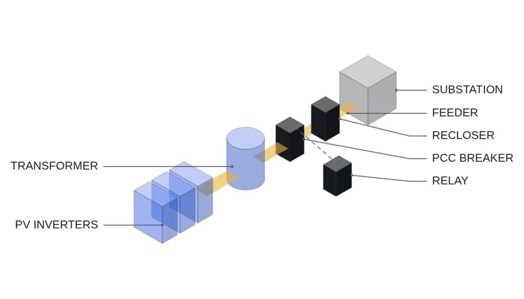
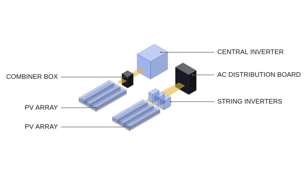
To state the conclusion first: for PV connected at the far end of a distribution feeder, a design that tries to hold down voltage rise with reactive power absorption alone (power factor control or Volt-VAR) underdelivers when the line’s X/R ratio is low. On a line dominated by resistance, reactive power can only lower the voltage a little, while inverter current and line losses go up. The decision order is check the line X/R ratio first; if it is low, make Volt-Watt (active power curtailment) the main tool, and if it is high, make Volt-VAR the main tool. Either way, the overvoltage protection relay stays as the final trip, independent of this control.
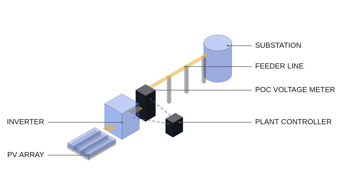
Safety interlocks: voltage control does not replace protection
Volt-VAR and Volt-Watt trim the voltage within the normal operating range. Voltage that has entered the protection zone is the relay’s job, and the settings of the two functions must not overlap.
- □ Confirm that the emergency off (EMO) opens the interconnection breaker and the inverter external-stop terminals through hardwiring. The plant power controller (PPC) only monitors the EMO loop state.
- □ Set the overvoltage relay pickup above the zero-output point of the Volt-Watt curve, so that control acts first and the relay stands behind it.
- □ Operate the inverter reactive power mode (fixed power factor, Volt-VAR, fixed reactive power) only in the mode required by the interconnection documents. Keep a record of setting changes to prevent unauthorized field changes.
- □ Confirm that the inverter returns to the default mode defined in the interconnection terms when upstream communication is lost. The exact default values are an item to verify against the interconnection documents.
- □ Check whether the inverter is set to reactive-power priority or active-power priority. When it hits its apparent power rating, this setting decides which output gets cut.
How much voltage reactive power can remove
Voltage rise at the point of connection is approximated as ΔV ≈ (P·R + Q·X) ÷ V. Active power P moves the voltage through resistance R, and reactive power Q moves it through reactance X. Assumptions: three-phase 22.9 kV line, equivalent R = 0.5 Ω, X = 0.4 Ω, PV output 1,000 kW, inverter rating 1,000 kVA.
The rise from active power is 1,000,000 W × 0.5 Ω ÷ 22,900 V ≈ 21.8 V. Absorbing 300 kvar gives −300,000 var × 0.4 Ω ÷ 22,900 V ≈ −5.2 V, cutting only about 24% of the rise. But adding 300 kvar to 1,000 kW takes apparent power to √(1,000² + 300²) ≈ 1,044 kVA, above rating, so with reactive-power priority the active power is cut to √(1,000² − 300²) ≈ 954 kW. Spending the same 46 kW on active power curtailment lowers the voltage by 46,000 W × 0.5 Ω ÷ 22,900 V ≈ 1.0 V, so under these assumptions reactive absorption is still more effective. On lines with a lower X/R ratio, that advantage shrinks.
| Method | Driving variable | Suited line | Cost |
|---|---|---|---|
| Fixed power factor | Reactive power proportional to output | Line with steady voltage margin | Absorbs reactive power even at low output |
| Volt-VAR | POC voltage | High X/R line | More inverter current and line loss |
| Volt-Watt | POC voltage | Low X/R line | Direct loss of generation |
The three methods in the table are not alternatives but a sequence. A typical configuration lets Volt-VAR act first, and if the voltage keeps rising after reactive power reaches its limit, Volt-Watt cuts output. The lower the line X/R, the less the Volt-VAR stage achieves, so starting Volt-Watt at a lower voltage gives better voltage management.
Setting flowchart
- From the interconnection documents, confirm the required mode, the voltage operating range, and the default mode on communication loss. Also check whether a standard that defines curve shapes, such as IEEE 1547-2018, applies.
- Obtain the R and X values of the line at the POC. If none are available, record POC voltage and output simultaneously and measure ΔV/ΔP and ΔV/ΔQ instead.
- Set the Volt-VAR deadband and slope, and decide whether active power takes priority at the inverter’s apparent power limit.
- Set the Volt-Watt start voltage and zero-output voltage, and confirm the margin to the overvoltage relay pickup.
- During commissioning, apply a reactive power step command, record the POC voltage change, and compare it with the calculated value.
PPC logic example
(* IEC 61131-3 ST pseudocode - combined Volt-VAR + Volt-Watt control (example values) *)
(* %I0.0   DI_EMO_LOOP_HEALTHY   : EMO hardwired loop healthy (1) - monitoring only *)
(* %I0.2   DI_OVR_59_TRIPPED     : overvoltage relay tripped (1) - relay trips breaker directly *)
(* %MD120  POC_V_PU              : POC voltage (pu) - measured via IEC61850_MMS or MODBUS_TCP *)
(* %MD124  PV_Q_SET_PU           : reactive power command (pu, absorption -) *)
(* %MD128  PV_P_LIMIT_PU         : active power ceiling command (pu) *)
(* %I0.6   DI_COMM_UPSTREAM_OK   : upstream communication healthy (1) *)

VAR CONSTANT
    V1 : REAL := 1.02;  V2 : REAL := 1.05;   (* Volt-VAR deadband end, full absorption voltage *)
    Q_MAX : REAL := 0.30;                    (* max absorption 0.30 pu *)
    V3 : REAL := 1.06;  V4 : REAL := 1.09;   (* Volt-Watt start, zero-output voltage *)
END_VAR

IF NOT DI_EMO_LOOP_HEALTHY OR DI_OVR_59_TRIPPED THEN
    PV_P_LIMIT_PU := 0.0; PV_Q_SET_PU := 0.0;       (* follow tripped state *)
ELSIF NOT DI_COMM_UPSTREAM_OK THEN
    MODE_DEFAULT := TRUE;                           (* revert to inverter built-in default - values per interconnection terms *)
ELSE
    MODE_DEFAULT := FALSE;
    (* Volt-VAR *)
    IF POC_V_PU <= V1 THEN PV_Q_SET_PU := 0.0;
    ELSIF POC_V_PU >= V2 THEN PV_Q_SET_PU := -Q_MAX;
    ELSE PV_Q_SET_PU := -Q_MAX * (POC_V_PU - V1) / (V2 - V1);
    END_IF;
    (* Volt-Watt *)
    IF POC_V_PU <= V3 THEN PV_P_LIMIT_PU := 1.0;
    ELSIF POC_V_PU >= V4 THEN PV_P_LIMIT_PU := 0.0;
    ELSE PV_P_LIMIT_PU := 1.0 - (POC_V_PU - V3) / (V4 - V3);
    END_IF;
END_IF;
(* overvoltage relay pickup set above V4 - control first, relay last *)
The curve voltages and reactive power limit are illustrative; actual values must follow the interconnection documents. When several inverters watch the same POC voltage and react at once, their controls can interact and make the voltage oscillate, so response time settings and any oscillation require waveform analysis and field measurement.
Boundary conditions
This judgment flips when line conditions change. If other generators connect to the same feeder, or the substation voltage regulation settings change, the reference for POC voltage itself moves, so the curve cannot be set once and forgotten. And if the curve is set without knowing the line’s R and X, the comparison in the calculation above does not hold.
The criterion is one sentence. Measure at the POC how much voltage 1 kvar of reactive power removes and how much 1 kW of curtailment removes, and make the larger one the main tool.