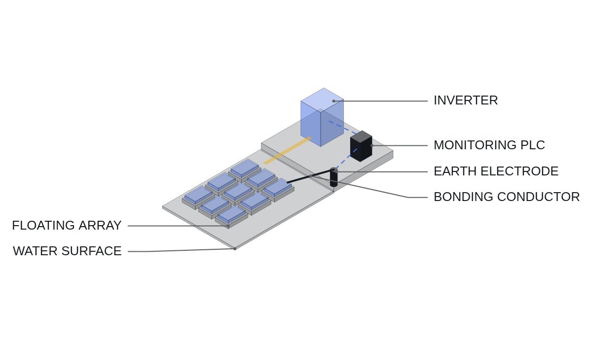
To state the conclusion first: in a floating PV installation, the first thing to fail is not insulation but the continuity of equipotential bonding. The floats are often made of insulating resin, so module frames do not touch the water directly, and the earth electrode sits on land. The bonding conductor linking frames to that electrode therefore runs a long way across the water surface and is flexed again and again by water-level changes and waves; if it breaks, a ground fault can raise frame potential without any protection operating. Leakage protection on water therefore starts by feeding bonding continuity monitoring, alongside insulation monitoring, into the interlock as an input.
Safety interlocks: the moment a person steps onto the floats
On land, an inspector stands on the ground; on water, the inspector stands on a float in the middle of the water. The touch voltage path in a shock and exposure to underwater potential after a fall both have to be considered, so interlock conditions are written around worker access.
- □ Confirm that the emergency off (EMO) opens the block’s AC breaker and inverter external-stop terminals through hardwiring. Place EMO buttons not only in the onshore control room but also at the entrance to the float walkway. The PLC only monitors the EMO loop.
- □ Confirm that opening the float access gate is preceded by the block’s inverter gate block and DC switch opening. Modules still produce voltage as long as they see light, so everything upstream of the switch remains live.
- □ If bonding continuity monitoring reports a fault, prohibit worker access to that block.
- □ For a block with an insulation monitoring device (IMD) alarm, prohibit access and block restart until the cause is found. Check IMD performance requirements against IEC 61557-8.
- □ Use IEC 60364-7-712 (PV power supply systems) as the basis for low-voltage installation requirements, and confirm any additional requirements for floating installations against the applicable national rules and the owner’s specification.
Electrical conditions on land versus on water
| Item | Ground-mount PV | Floating PV |
|---|---|---|
| Structure grounding | Racking driven into the ground | Floats insulated, bonding conductor to onshore electrode |
| Bonding conductor stress | Static | Repeated flexing from water level and waves |
| Humidity and condensation | Seasonal | Constantly humid, diurnal condensation |
| Cable routing | Fixed in trench or tray | Floating cable, possible water contact |
| Worker position | On the ground | On floats, surrounded by water |
| Leakage path | Spreads into the ground | Through water, resistance to electrode uncertain |
The rows unique to floating installations are bonding conductor stress and worker position. The others also exist on land to a lesser degree, but these two become interlock inputs only on water. With insulation monitoring alone and no bonding continuity monitoring, a ground fault can occur while the frame is detached from the electrode, leaving protection with nothing to judge by.
Construction and inspection checklist
- □ At every joint between floats, leave enough slack in the bonding conductor to absorb the water-level range, and use flexible conductors with crimped lugs.
- □ Form the bonding conductor as a loop with both ends brought out at the onshore electrode, so that a continuity monitor measures loop resistance continuously.
- □ Mount junction boxes and connectors at a height clear of the water surface, and select the protection rating by checking the manufacturer’s specification against the installation conditions.
- □ Support floating cables with buoyancy elements or trays so they do not sag into the water, and mark points where they rub against the mooring structure.
- □ Compare bonding loop resistance and insulation resistance trends quarterly. A stepwise rise in loop resistance is a precursor of a broken joint.
PLC logic example
(* IEC 61131-3 ST pseudocode - floating PV block A leakage, bonding, and access interlock *)
(* %I0.0   DI_EMO_LOOP_HEALTHY     : EMO hardwired loop healthy (1) - monitoring only, incl. walkway EMO *)
(* %I3.0   DI_IMD_A_ALARM          : block A insulation monitoring device alarm (1) *)
(* %I3.1   DI_ACCESS_GATE_A_OPEN   : block A float access gate open (1) *)
(* %I3.2   DI_DCSW_A_OPEN          : block A DC switch open (1) *)
(* %IW300  AI_BOND_LOOP_MOHM       : block A bonding loop resistance (milliohm) *)
(* %IW302  AI_A_DC_CURRENT_A       : block A DC current (A) *)
(* %M3.0   ACCESS_REQUEST_A        : HMI access request (1) *)
(* %Q3.0   DO_INV_A_GATE_BLOCK     : block A inverter stop *)
(* %Q3.1   DO_DCSW_A_TRIP          : block A DC switch trip (after current decay) *)
(* %Q3.2   DO_ACCESS_PERMIT_LAMP_A : block A access permit lamp *)
(* %Q3.3   DO_BOND_ALARM_A         : bonding continuity alarm *)

VAR CONSTANT R_BOND_MAX : INT := 500; END_VAR   (* example - set from as-built measurement *)

BOND_FAIL := (AI_BOND_LOOP_MOHM > R_BOND_MAX);
DO_BOND_ALARM_A := BOND_FAIL;

(* access request or gate open: stop the block first *)
STOP_REQ_A := DI_ACCESS_GATE_A_OPEN OR ACCESS_REQUEST_A OR DI_IMD_A_ALARM;
DO_INV_A_GATE_BLOCK := STOP_REQ_A;

TON_ZERO(IN := DO_INV_A_GATE_BLOCK AND (AI_A_DC_CURRENT_A < 1.0), PT := T#500MS);
DO_DCSW_A_TRIP := TON_ZERO.Q;            (* open after current stays decayed for 500 ms *)

(* access permit: EMO healthy + inverter stopped + DC switch open + bonding OK + no IMD alarm *)
DO_ACCESS_PERMIT_LAMP_A := DI_EMO_LOOP_HEALTHY AND DO_INV_A_GATE_BLOCK AND DI_DCSW_A_OPEN
                           AND NOT BOND_FAIL AND NOT DI_IMD_A_ALARM;
(* caution: modules and strings upstream of the switch stay live in daylight - lamp is not a dead-voltage indication *)
The 500 milliohm bonding loop limit is an example. The normal value itself depends on loop length and conductor cross-section, so the practical approach is to set a rate-of-rise criterion based on the as-built measurement.
Boundary conditions
There are cases where this design is overkill. If the float structure itself is metal, directly immersed, and its underwater grounding performance was verified at the design stage, a single broken bonding conductor does not mean loss of grounding. Conversely, the resistance of the underwater leakage path varies widely between fresh water and seawater and with water quality, so the underwater potential distribution requires waveform analysis and field measurement at each site.
The criterion is one sentence. If the path between frames and the earth electrode depends on a single moving conductor, monitor that conductor’s continuity as an interlock input of the same rank as insulation resistance.