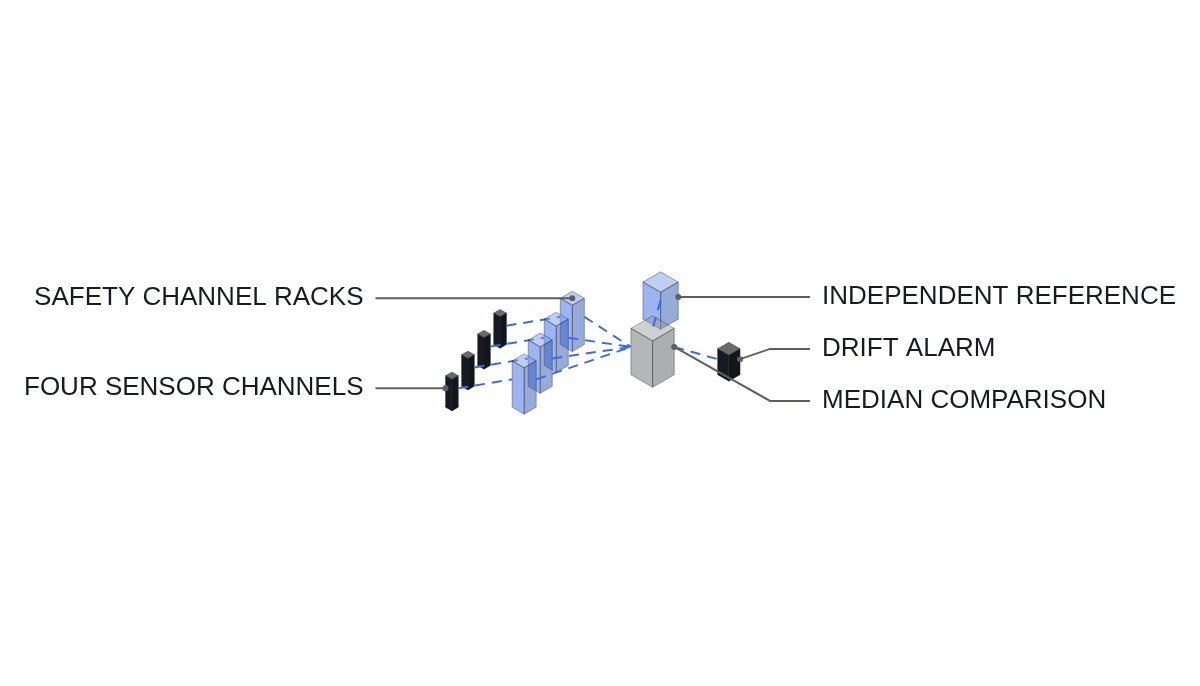
The short answer first. Drift in safety system instrument channels is not managed by calibration interval alone. Calibration is an after-the-fact guarantee that works because drift between calibrations has already been budgeted into setpoint uncertainty. What actually catches drift between calibrations is the channel check: comparing channels that measure the same variable against each other. But comparing channels only among themselves cannot see common drift, where every channel moves in the same direction. When you build channel comparison logic, one independent reference has to go in with it.
Start with the safety interlock conditions
Drift monitoring logic is a surveillance function that reads safety channel data and generates alarms. A structure in which this function feeds back into a safety channel’s trip decision or setpoint is not acceptable. Even when the monitoring is wrong, the protective function must keep working as designed.
- □ Confirm the channel comparison logic sits in the non-safety domain and receives data one-way from the safety channels.
- □ Confirm deviation alarms do not automatically bypass or trip a channel. Channel status changes happen only by operator judgment and procedure.
- □ Confirm a channel under calibration first follows the channel bypass procedure and is flagged as excluded in the comparison logic.
- □ Confirm the calibration standard’s traceability (to national standards) and validity period are recorded in the calibration record.
How setpoints and drift relate
A safety channel’s trip setpoint is not set in one step. Setpoint methodology in the ISA 67.04 family distinguishes three values: the analytical limit, where the safety analysis assumes protection acts; the allowable value, which goes into the technical specifications; and the trip setpoint actually entered into the instrument. The margin between analytical limit and trip setpoint covers sensor accuracy, process measurement error, environmental effects, and drift over the calibration interval.
In this structure, drift is a budget: “the channel may move this much within one calibration interval.” Lengthen the interval and the drift budget grows; grow the budget and the trip setpoint has to move farther from the analytical limit. Extending the calibration interval therefore eats operating margin, and any extension needs measured drift data over that period as its basis.
Surveillance types and action items
- Channel check: a qualitative comparison of indications between channels measuring the same variable. Performed at short intervals during operation.
- Channel functional test: inject a simulated signal and confirm the bistable and alarm/trip outputs operate at the setpoint.
- Channel calibration: adjust the whole channel, sensor included, against reference signals to restore accuracy.
- As-found / as-left records: keep both the pre-calibration value (as-found) and the post-calibration value (as-left). Drift trends are visible only in as-found data.
- Trend analysis: accumulate each channel’s as-found deviation over successive calibrations to see drift direction and size.
Item 4 is the one most often dropped in the field. If only as-left values are recorded, every entry reads “normal,” and the fact that a channel drifted to the limit in the same direction every interval vanishes from the record.
Channel comparison pseudocode (IEC 61131-3 ST)
(* I/O MAP - non-safety monitoring domain, one-way receive from safety channels *)
(* %IW30 : AI_CH_A_VAL   - channel A engineering value *)
(* %IW31 : AI_CH_B_VAL *)
(* %IW32 : AI_CH_C_VAL *)
(* %IW33 : AI_CH_D_VAL *)
(* %IW34 : AI_REF_INDEP  - independent reference (same variable estimated by a different principle) *)
(* %I7.0~%I7.3 : DI_CH_A_OOS ~ DI_CH_D_OOS  - excluded for calibration or bypass *)
(* %Q5.0~%Q5.3 : DO_CH_A_DEV_ALM ~ DO_CH_D_DEV_ALM  - per-channel deviation alarm *)
(* %Q5.4 : DO_COMMON_DRIFT_ALM                  - suspected common drift alarm *)

(* 1. Median of valid channels - median, not mean, so one outlier does not skew it *)
X_MED := MEDIAN_OF_VALID(AI_CH_A_VAL, AI_CH_B_VAL, AI_CH_C_VAL, AI_CH_D_VAL,
                         DI_CH_A_OOS, DI_CH_B_OOS, DI_CH_C_OOS, DI_CH_D_OOS);

(* 2. Per-channel deviation - R_DEV_TH above calibration tolerance, below setpoint margin *)
DO_CH_A_DEV_ALM := NOT DI_CH_A_OOS AND (ABS(AI_CH_A_VAL - X_MED) > R_DEV_TH);
DO_CH_B_DEV_ALM := NOT DI_CH_B_OOS AND (ABS(AI_CH_B_VAL - X_MED) > R_DEV_TH);
DO_CH_C_DEV_ALM := NOT DI_CH_C_OOS AND (ABS(AI_CH_C_VAL - X_MED) > R_DEV_TH);
DO_CH_D_DEV_ALM := NOT DI_CH_D_OOS AND (ABS(AI_CH_D_VAL - X_MED) > R_DEV_TH);

(* 3. Common drift - channels agree with each other but diverge from the independent reference *)
TON_COMMON(IN := ABS(X_MED - AI_REF_INDEP) > R_COMMON_TH, PT := T_COMMON);
DO_COMMON_DRIFT_ALM := TON_COMMON.Q;
(* Alarm only. No feedback into trip, bypass, or setpoint changes *)
The threshold range in comment 2 is the practical point. Set the threshold below calibration tolerance and normal in-tolerance differences between channels keep the alarm lit, and operators learn to ignore it. Set it above setpoint margin and by the time the alarm comes in, the channel may already be past its allowable value.
Detection capability by comparison basis
| Basis | Single outlier | Common drift | Effort |
|---|---|---|---|
| Channel mean | Detected (mean skewed) | Not detected | Low |
| Channel median | Detected | Not detected | Low |
| Independent reference | Indirect | Detected | Medium |
| Median + reference | Detected | Detected | Medium |
The table’s message is simple: no amount of layering channel-to-channel comparisons will reveal common drift. Channels of the same manufacturer, same model, and same calibration procedure cannot easily rule out common drift, so for variables that can be estimated by a different principle, such as reactor power (neutron flux instrumentation versus calorimetric thermal power), adding an independent reference comparison is the reasonable choice.
Boundary conditions
This design goes wrong when the independent reference is less trustworthy than the channels. If the reference is a calculated value, the errors and response lag of its inputs (flow, temperature, and so on) ride straight into it. During transients, the timing difference between reference and channel values opens up deviation, so common drift detection should be valid only during steady-state operation. The cause of deviation during transients requires waveform analysis and field measurement.
The single decision rule: add an independent reference comparison to channels whose variable can be estimated by a different principle, and defend the calibration interval with as-found trend analysis for channels that have no such estimate.