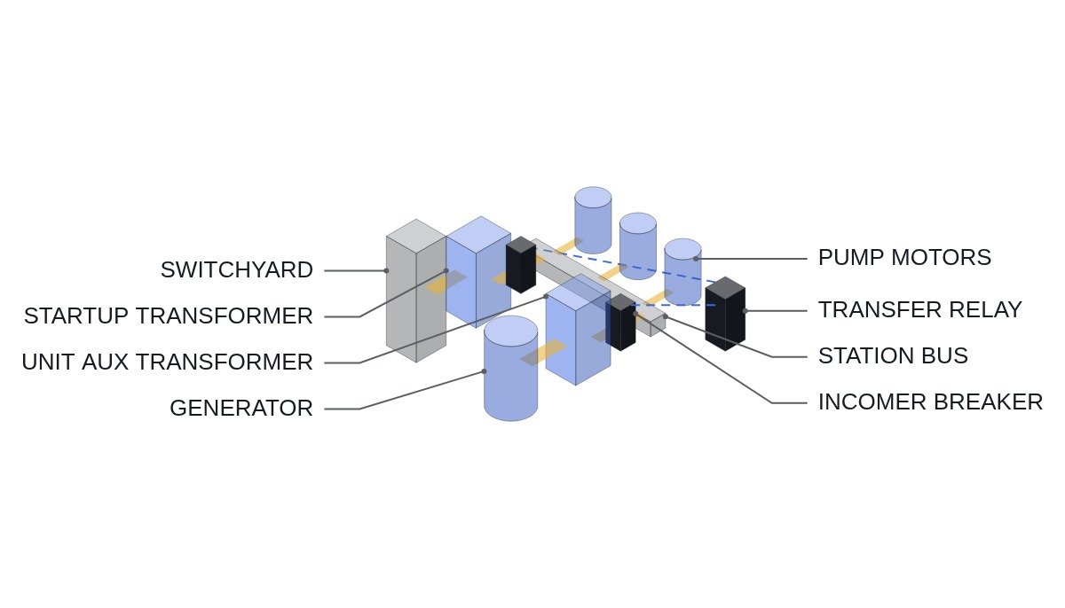
The short version: when a nuclear plant’s station service bus is transferred from the unit auxiliary transformer (UAT) to the startup transformer (SAT), the goal is not to close fast. The goal is to close either before the phase angle between the bus residual voltage and the new source opens up, or after the residual voltage has decayed far enough. Close anywhere between those two windows and the large pump motors on the bus take an out-of-phase closing torque on their shafts and windings. The first line of the transfer logic should therefore be a phase-angle and residual-voltage interlock, not a timer, and before any of that you should ask whether a transfer is needed at all, which depends on whether the unit has a generator circuit breaker (GCB).
Safety interlocks come first
This article covers normal and unplanned transfers of the non-safety medium-voltage station service buses (voltage levels such as 13.8 kV and 4.16 kV vary by unit). Class 1E buses and emergency diesel generator start logic are separate systems and are not discussed here. The transfer logic must never cross the following lines.
- □ No transfer after a bus fault trip (bus differential 87B or bus overcurrent). Energizing a faulted bus from the SAT spreads the fault to the startup transformer. Put the 86 lockout contact in series with the transfer permissive.
- □ No simultaneous closure of both incomers. Apart from the brief overlap in a planned transfer, paralleling the UAT and SAT incomers is blocked by a hardwired mutual interlock (cross-wired 52b contacts).
- □ Confirm the SAT source is healthy. If SAT primary voltage and frequency are not in their normal range, do not start the transfer. If the switchyard side is already unstable, the transfer only moves the problem.
- □ Manual override has priority. If the main control room selector is in “transfer blocked”, automatic transfer does not operate. The PLC reads this switch as an input, but the blocking circuit itself is hardwired.
- □ Emergency Off (EMO) circuits are independent of the transfer logic. Software monitors EMO status and never takes part in switching.
Transfer methods compared: what decides the close
When a generator trip removes the UAT source, the motors on the bus coast down on their own inertia and act as generators, holding up a residual voltage. That voltage drops in magnitude and frequency, and its phase angle relative to the new source keeps widening. Transfer methods differ in where along that trajectory they match the residual voltage to the new source.
| Method | Close criterion | Dead time | Main risk |
|---|---|---|---|
| Fast transfer | Close immediately within the small-angle initial window | Shortest | Breaker timing scatter pushes the close outside the window |
| In-phase transfer | Predict the angle trajectory, close near the first in-phase point | Medium | Slip prediction error; trajectory changes with bus load mix |
| Residual-voltage transfer | Close after residual voltage falls below setpoint | Long | Motor slowdown, process upset, re-acceleration inrush |
| Time-delay transfer | Close after a fixed timer | Setting-dependent | Out-of-phase torque if closed without checking residual voltage |
The table reads simply. If a fast transfer cannot be made, the next option is an in-phase transfer, and only when that also fails should the logic fall back to a residual-voltage transfer. A scheme that transfers on a time delay alone never looks at residual voltage, so if an existing plant still has one, adding a residual-voltage check is the first improvement to make.
A commonly cited acceptance limit is the ANSI C50.41 criterion on the vector difference between the motor residual voltage and the incoming voltage (1.33 pu V/Hz). That figure describes the motor’s tolerance, so the allowable phase angle in practice depends on the bus load mix and how the residual voltage decays. The decay curve has to be measured on each unit; it cannot be fixed from documents alone.
Transfer sequence flowchart
- Initiation check: a UAT source-loss signal (generator protection lockout 86G or UAT incomer undervoltage 27) and no bus fault (86B not operated).
- SAT source health: SAT secondary voltage normal, frequency normal, SAT breaker ready (spring charged, control power healthy).
- Send the UAT incomer open command and confirm 52b. No SAT close command goes out before the open is confirmed.
- Fast window check: if the phase angle is within limit and elapsed time is within the fast window, close the SAT breaker immediately.
- If the fast window is missed, switch to in-phase logic and close when the predicted angle enters the permitted band.
- If the in-phase window is also missed, switch to residual-voltage logic and close once bus voltage falls below setpoint. Large motors then go to a re-acceleration load-limiting routine (sequential restart).
- If the maximum wait time is exceeded, declare transfer failure: block the SAT close, raise an alarm, and hand the decision to the operator.
ST pseudocode: transfer permissive and method fallback
(* I/O MAP - non-safety station service bus A transfer panel *)
(* %I0.0  DI_UAT_52A_CLOSED     : UAT incomer breaker closed *)
(* %I0.1  DI_UAT_52B_OPEN       : UAT incomer breaker open *)
(* %I0.2  DI_SAT_52B_OPEN       : SAT incomer breaker open *)
(* %I0.3  DI_86G_TRIP           : generator protection lockout operated *)
(* %I0.4  DI_86B_TRIP           : bus protection lockout - transfer blocked *)
(* %I0.5  DI_SAT_BRK_READY      : SAT breaker spring charged, control power OK *)
(* %I0.6  DI_XFER_BLOCK_SW      : main control room transfer block switch *)
(* %I0.7  DI_EMO_STATUS         : EMO circuit status - monitoring only *)
(* %IW100 AI_BUS_RESID_V_PCT    : bus residual voltage, % of rated *)
(* %IW101 AI_PHASE_ANGLE_DEG    : bus-to-SAT phase angle, deg *)
(* %IW102 AI_SAT_V_PCT          : SAT secondary voltage, % *)
(* %Q0.0  DO_UAT_52_TRIP        : UAT incomer open command *)
(* %Q0.1  DO_SAT_52_CLOSE       : SAT incomer close command *)
(* %Q0.2  DO_XFER_FAIL_ALARM    : transfer failure alarm *)

(* 1. Permissive - denied on bus fault, manual block, or unhealthy SAT *)
XFER_PERMIT := NOT DI_86B_TRIP
               AND NOT DI_XFER_BLOCK_SW
               AND DI_SAT_BRK_READY
               AND (AI_SAT_V_PCT > R_SAT_V_MIN_PCT);

(* 2. Initiation - UAT source lost by generator lockout *)
IF DI_86G_TRIP AND XFER_PERMIT AND NOT XFER_ACTIVE THEN
    XFER_ACTIVE := TRUE;
    DO_UAT_52_TRIP := TRUE;
    T_XFER(IN := TRUE, PT := T#1500MS);  (* example maximum wait *)
END_IF;

(* 3. Close decision only after UAT open is confirmed - no paralleling *)
IF XFER_ACTIVE AND DI_UAT_52B_OPEN AND DI_SAT_52B_OPEN THEN
    IF T_XFER.ET < T#100MS
       AND ABS(AI_PHASE_ANGLE_DEG) < R_FAST_ANGLE_DEG THEN
        DO_SAT_52_CLOSE := TRUE;           (* fast transfer *)
        XFER_MODE := 1;
    ELSIF IN_PHASE_PREDICT_OK THEN
        DO_SAT_52_CLOSE := TRUE;           (* in-phase transfer *)
        XFER_MODE := 2;
    ELSIF AI_BUS_RESID_V_PCT < R_RESID_V_PCT THEN
        DO_SAT_52_CLOSE := TRUE;           (* residual-voltage transfer *)
        XFER_MODE := 3;
        MOTOR_RESTART_SEQ := TRUE;         (* hand large motors to sequential restart *)
    END_IF;
END_IF;

(* 4. Maximum wait exceeded - block close, operator decides *)
IF T_XFER.Q AND NOT DO_SAT_52_CLOSE THEN
    DO_XFER_FAIL_ALARM := TRUE;
    XFER_ACTIVE := FALSE;
END_IF;

(* 5. EMO status is logged only - transfer logic never operates EMO circuits *)
EV_LOG_EMO := DI_EMO_STATUS;
R_FAST_ANGLE_DEG, R_RESID_V_PCT, the 100 ms fast window and the 1500 ms maximum wait are all illustrative values. Real values come from measured breaker operating times and the bus residual-voltage decay curve. If the phase angle reaches the PLC as an analog input, the decision lags by a scan cycle, so the usual split is to leave the fast-transfer decision to a dedicated transfer relay and have the PLC handle permissives, monitoring and logging.
Commissioning checklist
- □ Measure the open and close times of the UAT and SAT incomers at least three times each and record the scatter. Size the fast window to include it.
- □ Record the residual-voltage decay waveform with the bus loaded in its real operating configuration. Do not use no-load test waveforms.
- □ Confirm the steady-state phase difference between the SAT and UAT sources (including transformer vector group differences) and zero the phase-angle input accordingly.
- □ Simulate an 86B operation and confirm the transfer does not start.
- □ Operate the transfer block switch and confirm automatic transfer is inhibited and the inhibit is annunciated in the main control room.
- □ After a residual-voltage transfer, confirm from current waveforms that large pump motors restart in sequence and that simultaneous re-acceleration does not overload the SAT. Whether noise causes false phase detection requires waveform analysis and field measurement.
Boundary conditions: when this transfer design is wrong
First, units with a generator circuit breaker. With a GCB between the generator and the main transformer, a generator trip opens only the GCB, and the UAT keeps being back-fed from the grid through the main transformer. In that case a generator trip is not a transfer initiator; a transfer is needed only for a fault in the main transformer or UAT, or for loss of the switchyard side. Keying initiation on 86G would cause unnecessary transfers.
Second, a major change in the bus load mix. When large motors are replaced or the share of variable-speed drive load grows, the residual-voltage decay changes. Drive loads contribute almost no residual voltage on loss of supply, so the phase angle can open faster. A window set from old commissioning waveforms is no longer valid.
Third, handling the transfer decision entirely inside the PLC scan. If scan time and analog conversion delay are not negligible against the fast window, a “fast” transfer effectively degrades into an in-phase or residual-voltage transfer.
The single decision rule: if you cannot define the fast window from measured breaker timing scatter and a residual-voltage decay curve taken under real load, do not claim fast transfer; design around a transfer that confirms residual voltage first.