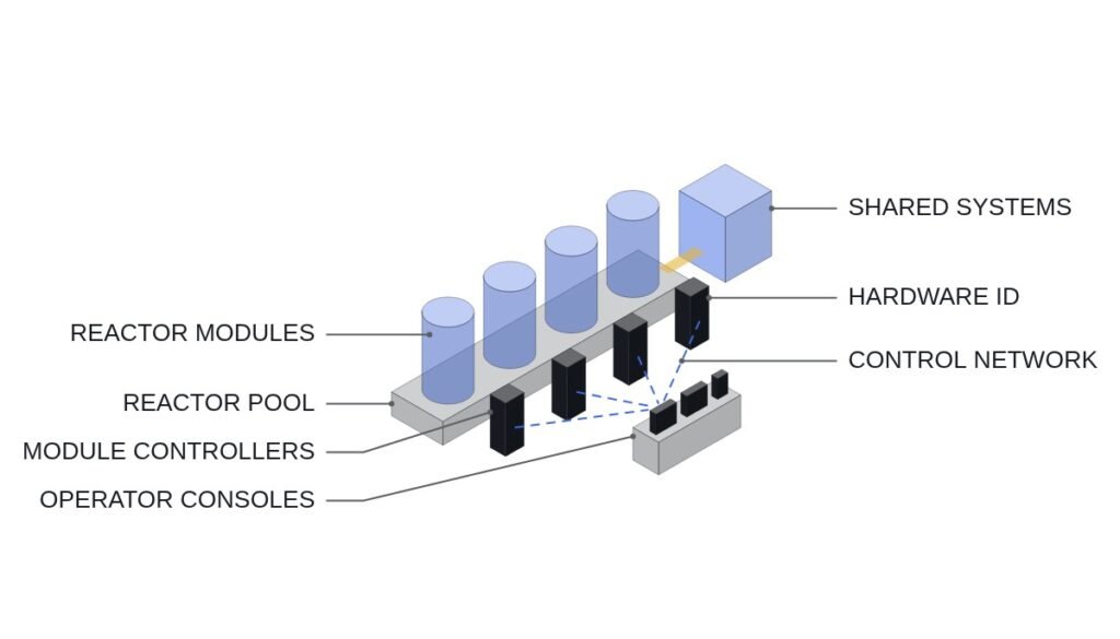
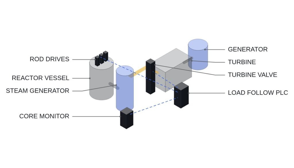
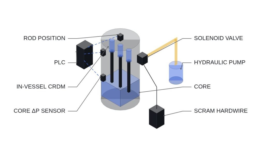
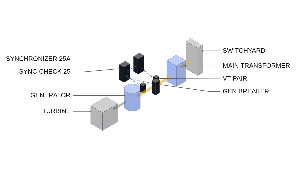
The short version: what prevents accidents when synchronizing a nuclear main generator is not the precision of the auto-synchronizer (25A). It is a sync-check relay (25), physically independent of the auto-synchronizer, wired in series in the close circuit. The auto-synchronizer works out when to close; the sync-check relay can veto a close that should not happen now. Put both functions in one device or one PLC routine and a single malfunction of that device becomes an out-of-phase close, with the long turbine-generator shaft train taking the full impact.
Safety interlocks come first
Here are the conditions a synchronizing close command passes through before it reaches the breaker close coil, organized around the close circuit. These must exist as series contacts in the hardwired close circuit, independent of PLC logic; the PLC reads the state of each contact and shows it to the operator.
- □ Confirm the sync-check relay (25) permissive contact is in series in the close circuit. The auto-synchronizer’s close output alone must not be able to energize the coil.
- □ No dead-bus closing. A generator breaker has no reason to close with the grid side de-energized, so disable the 25 relay’s dead-bus permissive for generator breakers.
- □ Generator protection lockout (86G) not operated, field breaker (41) closed, breaker ready (spring charged, gas pressure normal).
- □ Single synchronizing selection. Where several breakers share one synchronizer, build the selector switches with a hardwired mutual interlock so two breakers cannot be selected at once.
- □ Manual synchronizing does not bypass the 25 permissive either. If a bypass switch exists, make it a key switch and log every use.
- □ EMO circuits open the breaker through hardwiring only; synchronizing logic just monitors their status.
Three conditions and the breaker closing time
Synchronizing requires matching three quantities: voltage difference, frequency difference (slip) and phase angle. For large turbine generators, the IEEE C50.13 recommended ranges are widely quoted as ±10° phase angle, 0 to +5% voltage difference and ±0.067 Hz frequency difference, but actual settings follow the generator manufacturer’s requirements and each unit’s setting standards first. The more important practical item is breaker closing time.
The auto-synchronizer allows for the time between issuing the close command and the breaker contacts actually touching, so it issues the command before the angle reaches 0°. That advance angle is the product of slip and closing time. Assumption: with 0.05 Hz slip and 100 ms closing time, the advance angle is 360° × 0.05 Hz × 0.1 s = 1.8°. As closing time lengthens with age, the actual closing angle drifts late by the same amount.
| Device | Role | Output | If it fails alone |
|---|---|---|---|
| Auto-synchronizer 25A | Adjusts AVR and governor, computes advance angle | Close command | Command issued at the wrong moment |
| Sync-check 25 | Checks the three-condition window | Permissive contact | No permit (fail-safe) or permanent permit |
| Manual synchroscope | Operator visual judgment | None (indication) | Misjudgment |
| PLC monitoring | Displays, logs, alarms | Alarm and permit indication | Wrong display, no effect on closing |
The column to read is the last one. For no single device failure to cause an out-of-phase close, the device that issues the close command and the device that grants the permit must be different hardware. That is why the PLC sits at the monitoring level rather than in either role.
Synchronizing flowchart
- Confirm turbine at rated speed, field applied, generator terminal voltage established.
- Select the breaker to be synchronized (confirm only one is selected).
- Start the auto-synchronizer: trim voltage difference through the AVR and frequency difference through the governor. Set generator frequency slightly above grid frequency so there is no reverse power right after closing.
- Confirm the sync-check relay is inside its window (permissive contact closed).
- The auto-synchronizer issues the close command at the advance angle.
- After confirming 52a, pick up initial load. Raise active power output before reverse power protection (32) can act.
- On close failure (no 52a within the set time after the command), drop the command and alarm; retry is at the operator’s discretion.
ST pseudocode: synchronizing monitoring and logging
(* I/O MAP - synchronizing monitoring PLC, close circuit itself is hardwired *)
(* %I2.0  DI_25_PERMIT           : sync-check permissive contact status *)
(* %I2.1  DI_25A_CLOSE_CMD       : auto-synchronizer close output, monitored *)
(* %I2.2  DI_GEN_52A_CLOSED      : generator breaker closed *)
(* %I2.3  DI_86G_TRIP            : generator lockout *)
(* %I2.4  DI_41_FIELD_BRK_CLOSED : field breaker closed *)
(* %I2.5  DI_SYNC_SEL_SINGLE     : single sync selection confirmed *)
(* %I2.6  DI_BRK_READY           : breaker ready - spring, gas pressure *)
(* %I2.7  DI_SYNC_BYPASS_KEY     : 25 bypass key switch - monitoring only *)
(* %IW300 AI_DELTA_V_PCT         : voltage difference, % *)
(* %IW301 AI_SLIP_MHZ            : frequency difference, mHz *)
(* %IW302 AI_DELTA_ANGLE_DEG     : phase difference, deg *)
(* %Q2.0  DO_SYNC_READY_LAMP     : sync ready indication *)
(* %Q2.1  DO_CLOSE_FAIL_ALARM    : close failure alarm *)
(* %Q2.2  DO_BYPASS_ALARM        : bypass in use alarm *)

(* 1. Ready conditions - indication only, close decision is hardwired *)
SYNC_READY := NOT DI_86G_TRIP AND DI_41_FIELD_BRK_CLOSED
              AND DI_SYNC_SEL_SINGLE AND DI_BRK_READY;
DO_SYNC_READY_LAMP := SYNC_READY AND DI_25_PERMIT;

(* 2. Snapshot conditions at the instant the close command appears *)
IF R_TRIG(DI_25A_CLOSE_CMD) THEN
    LOG_DV    := AI_DELTA_V_PCT;
    LOG_SLIP  := AI_SLIP_MHZ;
    LOG_ANGLE := AI_DELTA_ANGLE_DEG;
    LOG_PERMIT_AT_CMD := DI_25_PERMIT;   (* record whether a command came without permit *)
    T_CLOSE(IN := TRUE, PT := T#300MS);  (* example close confirmation wait *)
END_IF;

(* 3. For actual closing angle - record phase difference on 52a rising edge *)
IF R_TRIG(DI_GEN_52A_CLOSED) THEN
    LOG_ANGLE_AT_CLOSE := AI_DELTA_ANGLE_DEG;
    LOG_CLOSE_TIME_MS  := TIME_TO_INT(T_CLOSE.ET);
    T_CLOSE(IN := FALSE);
END_IF;

(* 4. Close failure *)
IF T_CLOSE.Q AND NOT DI_GEN_52A_CLOSED THEN
    DO_CLOSE_FAIL_ALARM := TRUE;
    T_CLOSE(IN := FALSE);
END_IF;

(* 5. Bypass key use is alarmed and logged only - the PLC never performs a bypass *)
DO_BYPASS_ALARM := DI_SYNC_BYPASS_KEY;
The purpose of this logic is not to close the breaker but to catch aging drift in breaker closing time. As LOG_CLOSE_TIME_MS accumulates start after start, a rising trend in closing time becomes visible, and that is the signal to reset the advance angle. The 52a auxiliary contact does not change state at exactly the same moment as the main contacts, so the precise closing angle has to be confirmed from voltage waveforms on a disturbance recorder; the PLC log is for trending.
Pre-start checklist
- □ Confirm from the wiring diagram and the physical terminals that the 25 permissive contact is in series in the close circuit.
- □ Print the 25 relay settings and confirm the dead-bus permissive is disabled.
- □ Confirm the phase reference (connection and polarity) of the generator-side and grid-side PTs, and that phase shift compensation for the main transformer vector group is in the settings.
- □ Compare closing time records from the last three starts for an upward trend.
- □ Check custody and use records for the bypass key switch.
- □ Review the current waveform right after closing for abnormal inrush. Whether PT secondary noise causes phase misjudgment requires waveform analysis and field measurement.
Boundary conditions: when this arrangement is wrong
First, whether a unit synchronizes on the generator circuit breaker (GCB) or on a switchyard breaker varies. When synchronizing on a GCB, the main transformer is already energized from the grid, so the phase-comparison PT locations and transformer phase-shift compensation differ. When synchronizing on switchyard breakers and either of two breakers can be used, as in a breaker-and-a-half scheme, each breaker has its own closing time and its own advance angle to manage.
Second, products that integrate the sync-check relay and auto-synchronizer in one box. Even if the functions are separated internally, shared power supply, CPU and PT inputs mean independence does not hold against common-cause failure. Adding a separate 25 relay is what keeps the premise of this article intact.
The single decision rule: if the device that issues the close command and the device that grants the close permit are not independent all the way through power supply, inputs and processing, the synchronizing interlock is not finished.