The short version: breaker failure protection (50BF) in a nuclear switchyard goes wrong in two places if you build it with ordinary substation logic. One is a generator-side breaker receiving a trip command while carrying almost no current (for example, a reverse power trip after a turbine trip). The other is a trip zone in which one breaker failure takes out two offsite power circuits at once. Detect failure by current alone and you miss the first; skip checking the trip map against offsite power independence and you miss the second.
Safety interlocks come first
Switchyard protection is grid protection and, at the same time, protection of the plant’s offsite power supply paths. So not tripping more than necessary matters as much as tripping fast. The conditions below are the premises of the protection logic design.
- □ 50BF is initiated only by protective relay trip outputs. Operator manual open commands do not initiate 50BF (a failed manual open is handled as an alarm).
- □ Failure is detected by current detection (50) or the breaker auxiliary contact (52a); for generator-related breakers, the two paths are ORed.
- □ Re-trip first. Before failure is declared, send a second trip through the same breaker’s second trip coil.
- □ On confirmed failure, trip adjacent breakers, operate the 86BF lockout and, where needed, send direct transfer trip (DTT) to the remote end. Make 86BF manual reset.
- □ Where bus differential (87B) and 50BF share a lockout, document the reset procedure.
- □ Protective relay trip circuits and EMO circuits are hardwired; the monitoring PLC only logs status.
Failure impact by breaker position in a breaker-and-a-half scheme
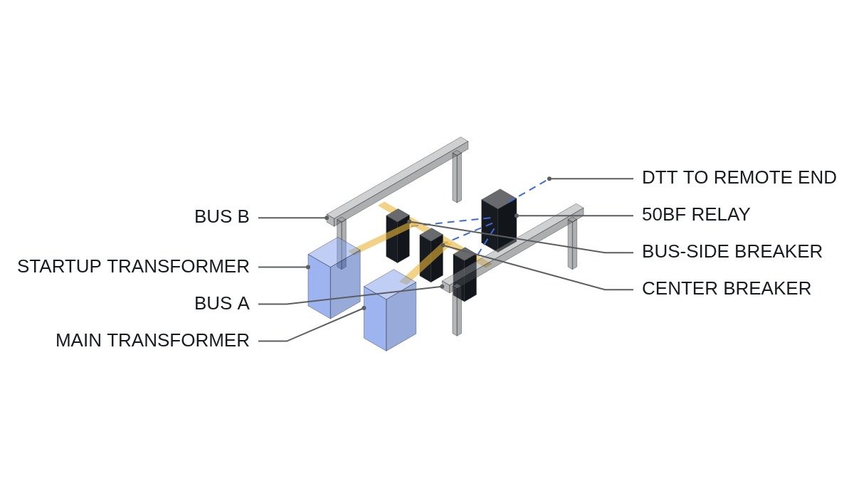
Large plant switchyards often use a breaker-and-a-half scheme: three breakers form a bay between two buses, with two circuits connected between them. How much is lost when one breaker fails depends on whether it is a bus-side or center (tie) breaker.
| Failed breaker | Additional trips | Circuits lost | Plant impact |
|---|---|---|---|
| Bus side (A) | All breakers on bus A | One circuit in that bay | Supply held via the other bus |
| Center (tie) | Both outer breakers in the bay + remote DTT | Both circuits in that bay | If they are generator and offsite, both lost together |
| Bus side (B) | All breakers on bus B | One circuit in that bay | Supply held via the other bus |
The lesson sits in the center breaker row. If the main generator circuit and an offsite power (startup transformer) circuit share a bay, a single center breaker failure loses generation and offsite power together. When writing the 50BF trip map, look beyond the protection zones and confirm that offsite power circuits are in different bays. That arrangement is set at the design stage, but it is also the first thing a protection engineer can catch when reviewing the trip map.
50BF decision flowchart
- Initiate: receive a protective relay trip output (87, 21, 87G, etc.). Manual opens excluded.
- Immediate re-trip: trip command through the same breaker’s second trip coil.
- Start the failure timer. Set it as the sum of rated breaker interrupting time, current detector reset time and margin.
- On timer expiry, if current detection (50) is still picked up or 52a is still closed, declare failure.
- Confirmed failure: trip adjacent breakers per the trip map, operate 86BF, send remote DTT where needed.
- Log: failed breaker, detection path (current or contact), elapsed time.
ST pseudocode: center breaker 50BF logic
(* I/O MAP - bay 2 center breaker CB2 failure protection, logic view for review and test *)
(* %I3.0  DI_PROT_TRIP_CB2      : protective relay trip output - 50BF initiate *)
(* %I3.1  DI_CB2_52A_CLOSED     : CB2 auxiliary contact closed *)
(* %I3.2  DI_CB2_50_PICKUP      : CB2 current detector picked up *)
(* %I3.3  DI_BAY2_GEN_LINE      : bay 2 circuit is a generator circuit - setting input *)
(* %I3.4  DI_86BF_RESET_PB      : 86BF manual reset pushbutton *)
(* %Q3.0  DO_CB2_RETRIP         : CB2 second trip coil re-trip *)
(* %Q3.1  DO_CB1_TRIP           : adjacent breaker CB1 trip *)
(* %Q3.2  DO_CB3_TRIP           : adjacent breaker CB3 trip *)
(* %Q3.3  DO_DTT_SEND           : remote transfer trip - IEC61850_GOOSE or dedicated channel *)
(* %Q3.4  DO_86BF_OPERATE       : 86BF lockout *)

(* 1. Immediate re-trip on initiation *)
IF DI_PROT_TRIP_CB2 THEN
    DO_CB2_RETRIP := TRUE;
    BF_TMR(IN := TRUE, PT := T#150MS);  (* example - interrupt time + reset + margin *)
END_IF;

(* 2. Failure detection - generator circuit uses current OR contact, others current only *)
IF DI_BAY2_GEN_LINE THEN
    CB2_NOT_OPEN := DI_CB2_50_PICKUP OR DI_CB2_52A_CLOSED;
ELSE
    CB2_NOT_OPEN := DI_CB2_50_PICKUP;
END_IF;

(* 3. Confirmed failure - adjacent trips, DTT, lockout *)
IF BF_TMR.Q AND CB2_NOT_OPEN THEN
    DO_CB1_TRIP    := TRUE;
    DO_CB3_TRIP    := TRUE;
    DO_DTT_SEND    := TRUE;
    DO_86BF_OPERATE := TRUE;           (* manual reset type *)
END_IF;

(* 4. Drop initiation - trip output gone and breaker open, reset timer *)
IF NOT DI_PROT_TRIP_CB2 AND NOT CB2_NOT_OPEN THEN
    BF_TMR(IN := FALSE);
    DO_CB2_RETRIP := FALSE;
END_IF;

(* 5. 86BF reset by pushbutton only, after CB2 open is confirmed *)
IF DI_86BF_RESET_PB AND NOT CB2_NOT_OPEN THEN
    DO_86BF_OPERATE := FALSE;
END_IF;
In practice 50BF is implemented as a function inside the protective relay or as a dedicated relay; this pseudocode expresses the logic for review and testing. The 150 ms is illustrative; the real timer comes from rated breaker interrupting time and system stability studies. ORing 52a on generator circuits prevents a missed failure when the 50 element does not pick up at low current, but it adds a misoperation risk from poorly adjusted auxiliary contacts, so periodic contact checks are a precondition.
Trip map review checklist
- □ Tabulate the two circuits in each bay by function (generator, offsite power, transmission line) and check whether any bay carries two offsite power circuits.
- □ Tabulate the additional trip zone for each breaker failure and check it against the actual wiring.
- □ Confirm 52a is in the 50BF detection path for generator-related breakers.
- □ Confirm the re-trip output goes to the second trip coil on separate control power.
- □ Check DTT channel redundancy and the alarm on channel loss. Channel latency and error rate require field measurement.
- □ Confirm there is a reset procedure after 87B and 50BF operation and that authority to reset 86 lockouts is clear.
Boundary conditions: when this design is wrong
First, with a double-bus or ring-bus switchyard, the trip zones in the table do not apply as written. In a ring bus one breaker failure drops the two circuits on either side, so the circuit placement principle holds, but it is reviewed by ring order instead of by bay.
Second, generator circuits with a generator circuit breaker (GCB). Low-current trips mostly happen at the GCB, so the 52a OR logic on switchyard breakers becomes less necessary and may leave only the misoperation risk. In that case put the 52a path in the GCB’s 50BF and run the switchyard breakers mainly on current detection.
Third, carrying the old 50BF timer straight over when protective relays are replaced. If the new relay’s current detector reset time differs, the same timer value gives a different margin.
The single decision rule: do the final review of a 50BF trip map not by protection zone but by asking “how many offsite power paths are left when one breaker fails?”