Bottom line first. What separates N+1 from 2N UPS redundancy is not the module count but where the single point of failure is left. N+1 absorbs the loss of one UPS module, yet the parallel output bus, the output switchboard and the parallel control wiring still exist only once. 2N splits that whole path into two. And what happens more often on site is not a design choice but drift during operation: as load grows, an N+1 system quietly drops to N without raising an alarm. Redundancy has to be judged from load ratio, not from the number of modules running.
Safety interlocks first — the checking order for parallel UPS
Interlocks in a parallel UPS start from one question: which breakers must never be closed at the same time? When one module is isolated or the load is moved to maintenance bypass, tying an inverter output and the bypass source onto the same bus while they are not synchronized produces circulating current and a disturbed load voltage. The items below must hold through hardwired or mechanical key interlocks before any PLC logic comes into play.
- EMO (Emergency Off) is hardwired directly into the trip circuits of each UPS and of the parallel output switchboard. The PLC only reads the EMO chain status; the code contains no path to reset, delay or bypass it.
- The maintenance bypass breaker (MBB) and the UPS output breaker (UOB) are prevented from closing together by a mechanical key interlock. The key sequence is “confirm UPS on static bypass → close MBB → open UOB”, and the reverse on return.
- A module is isolated in the order “stop that module’s inverter → confirm its output breaker open (52b contact) → open input and battery breakers”. On re-entry, the output breaker closes only after the inverter has synchronized to the parallel bus.
- Confirm from the manufacturer’s specification what state a module goes to if the parallel control wiring (load sharing and sync signals) is cut: isolation of that module or transfer of the whole system to static bypass. This differs between manufacturers, so it is an item to verify.
- A module with its battery breaker open cannot carry load in an outage. Include this in the judgment so that “redundancy healthy” is never shown in that state.
How N+1 and 2N differ structurally
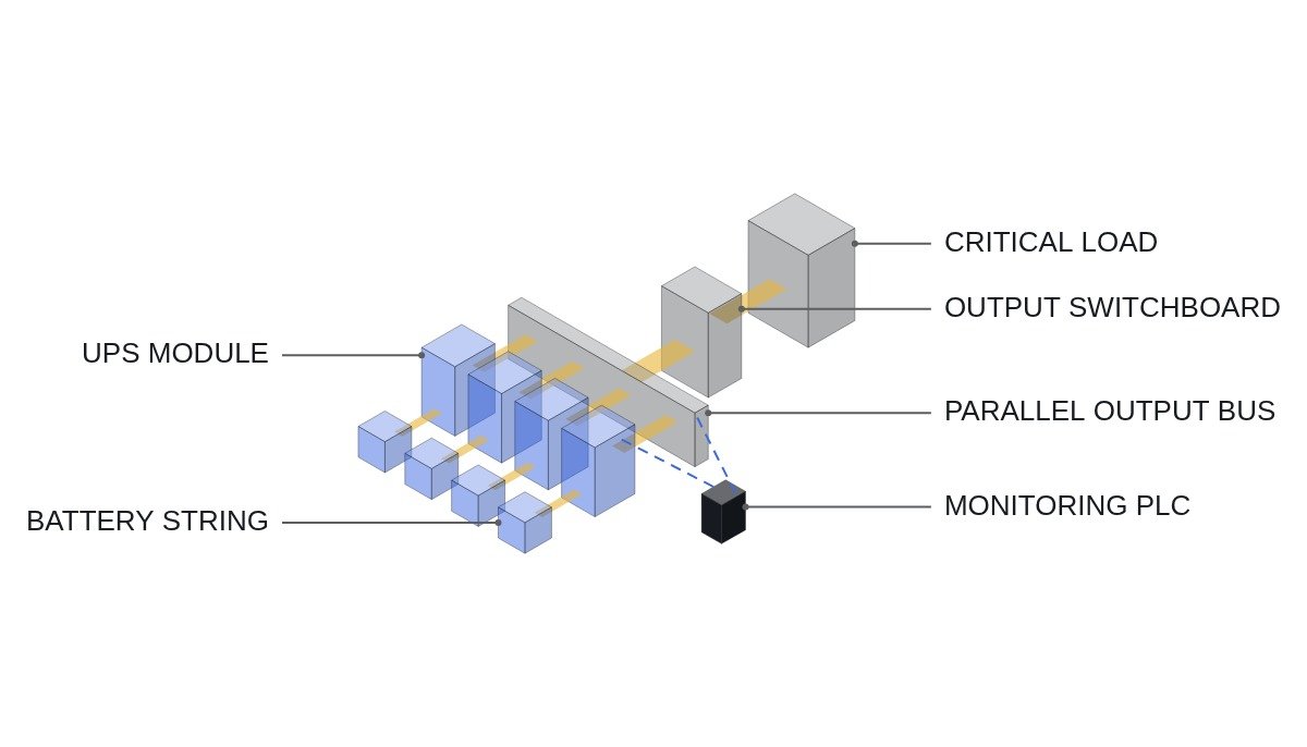
N+1 is a parallel configuration with one module more than the N required by the load. All modules feed a single parallel bus and share the load equally. If one drops out, the remaining N carry the full load, so redundancy holds against a module failure.
2N is two independent systems (A and B), each sized for the full load. Loads take power from both sides at once through dual power inputs (dual cord), or, if they have a single input, through an STS. If system A disappears entirely, system B keeps the load running. Having two parallel buses, two output switchboards and two downstream distribution boards is the essential difference from N+1.
One point is easy to miss. 2N redundancy only carries all the way through when the load has two inputs. If single-input loads are fed from one STS, the STS itself becomes a single point of failure again. A 2N purchase that merges into one line right in front of the load is effectively “2N up to the UPS only”.
Judging redundancy from load ratio
The N+1 redundancy condition comes from a simple expression. With module rating P_M, N+1 modules installed and load P_L, surviving the loss of one module requires P_L ≤ N × P_M. Expressed as per-module loading in normal operation, that is N/(N+1) or less.
- Assumption: 200 kW modules in a 3+1 configuration (four in total). Redundancy limit = 3 × 200 = 600 kW; per-module loading limit in normal operation = 3/4 = 75 %.
- If the load grows to 640 kW under the same conditions, per-module loading is 80 %. All four modules are healthy, so there is no alarm. But if one fails, three modules have to take 640 kW, about 107 % each, and the system goes into overload operation or transfers to static bypass.
- For 2N, the loading limit is 50 % per system. If each side carries 55 %, losing one side puts the other at 110 %.
“4/4 modules healthy” on the local panel is not a redundancy status. Redundancy is a derived value that needs both load ratio and module count. Unless a supervisory PLC calculates it separately and raises it as an alarm, added servers or equipment will silently use up the redundancy.
Redundancy-loss logic (ST pseudocode)
(* I/O MAP *)
(* %I0.0  DI_EMO_CHAIN_OK       : EMO hardwired chain healthy - status monitoring only *)
(* %I0.1  DI_UPS1_ON_INV        : UPS1 supplying from inverter *)
(* %I0.2  DI_UPS2_ON_INV        : UPS2 supplying from inverter *)
(* %I0.3  DI_UPS3_ON_INV        : UPS3 supplying from inverter *)
(* %I0.4  DI_UPS4_ON_INV        : UPS4 supplying from inverter *)
(* %I0.5  DI_MBB_CLOSED         : maintenance bypass closed - contact after key interlock *)
(* %I0.6  DI_BATT_CB_ALL_CLOSED : all module battery breakers closed - series contacts *)
(* %IW100 AI_LOAD_KW            : parallel bus load kW - power meter via MODBUS_TCP *)
(* %M10.0 X_MODBUS_LINK_OK      : power meter comms healthy - internal status bit *)
(* %Q0.0  DO_REDUNDANCY_LOST    : redundancy lost alarm *)
(* %Q0.1  DO_LOAD_ADD_INHIBIT   : load addition inhibit signal - to operations *)

R_MODULE_KW := 200.0;   (* module rating - assumed value *)
R_MARGIN    := 0.95;    (* early-warning margin - example value *)

I_ONLINE := BOOL_TO_INT(DI_UPS1_ON_INV) + BOOL_TO_INT(DI_UPS2_ON_INV)
          + BOOL_TO_INT(DI_UPS3_ON_INV) + BOOL_TO_INT(DI_UPS4_ON_INV);

(* capacity left after losing one module *)
R_CAP_AFTER_LOSS := INT_TO_REAL(I_ONLINE - 1) * R_MODULE_KW;

(* on comms loss, do not trust the load value - treat as redundancy lost, alarm-safe side *)
IF NOT X_MODBUS_LINK_OK THEN
    B_LOAD_OVER := TRUE;
ELSE
    B_LOAD_OVER := AI_LOAD_KW > (R_CAP_AFTER_LOSS * R_MARGIN);
END_IF;

B_REDUNDANT := DI_EMO_CHAIN_OK
               AND DI_BATT_CB_ALL_CLOSED
               AND NOT DI_MBB_CLOSED          (* no redundancy while on bypass *)
               AND NOT B_LOAD_OVER;

(* 10 s delay so load transients do not make the alarm flicker - example value *)
TON_RED(IN := NOT B_REDUNDANT, PT := T#10S);
DO_REDUNDANCY_LOST  := TON_RED.Q;
DO_LOAD_ADD_INHIBIT := B_LOAD_OVER;
R_MODULE_KW, R_MARGIN and the 10 s delay are illustrative assumptions. Where the load value arrives over MODBUS_TCP, the key point is that a communication loss must never be read as “load normal”. The causes of load-sharing imbalance between modules or of communication errors are not asserted here; they require waveform analysis and field measurement.
N+1 versus 2N
| Item | N+1 | 2N |
|---|---|---|
| Failure absorbed | One UPS module | One entire UPS system |
| Remaining SPOF | Parallel bus, output board, parallel control wiring | STS/PDU ahead of single-input loads |
| Normal loading limit | N/(N+1), 75 % for 3+1 | 50 % per system |
| Output board maintenance | Load moved to maintenance bypass | Work with one system shut down |
| Equipment | N+1 modules, one output board | 2N modules, two output boards |
| Load requirement | Single-input loads acceptable | Dual input needed to complete it |
The row to read before cost is “output board maintenance”. N+1 is strong against module failures, but any work on the parallel bus or output board means putting the load on maintenance bypass, which is utility power without UPS protection. During that time redundancy is zero. If the maintenance plan repeatedly calls for bus outages, assume the N+1 redundancy disappears every maintenance cycle.
Design and operation checklist
- □ Have the kW of dual-input and single-input loads been totalled separately from the load list?
- □ If single-input loads are fed through an STS, is the STS named as a single point of failure and has distributed placement been considered?
- □ Is the redundancy limit load (N × P_M; for 2N, 50 % of the per-system rating) entered as a setpoint in the monitoring system?
- □ Is the load-ratio early warning set at around 90–95 % of the limit load?
- □ Is a parallel-control-wiring break test in the acceptance procedure, and was the wiring actually disconnected to confirm the behaviour?
- □ Is the maintenance bypass key interlock sequence posted on a nameplate at the equipment?
- □ Does an open battery breaker feed into the redundancy judgment?
- □ Has the maximum number of units that can be paralleled (product limit) been confirmed before planning an expansion?
Boundary conditions — where this judgment flips
N+1 wins where most loads are single-input, parallel bus outages are rare, and load growth is predictable enough to manage the limit load. Installing 2N there adds little redundant path for the extra investment if everything merges through an STS in front of the load.
Conversely, 2N wins where loads have dual inputs and output and distribution boards must be maintained without shutting the load down. There is also an efficiency counterargument: 2N runs at 50 % or less per system, so it operates in the light-load part of the efficiency curve. The actual loss difference has to be calculated from the product efficiency curves and real load; it cannot be settled in general terms.
The single decision rule: if the load is dual-input and non-stop maintenance is required all the way to the output board, choose 2N; otherwise choose N+1, but always attach a load-ratio-based redundancy-loss alarm.