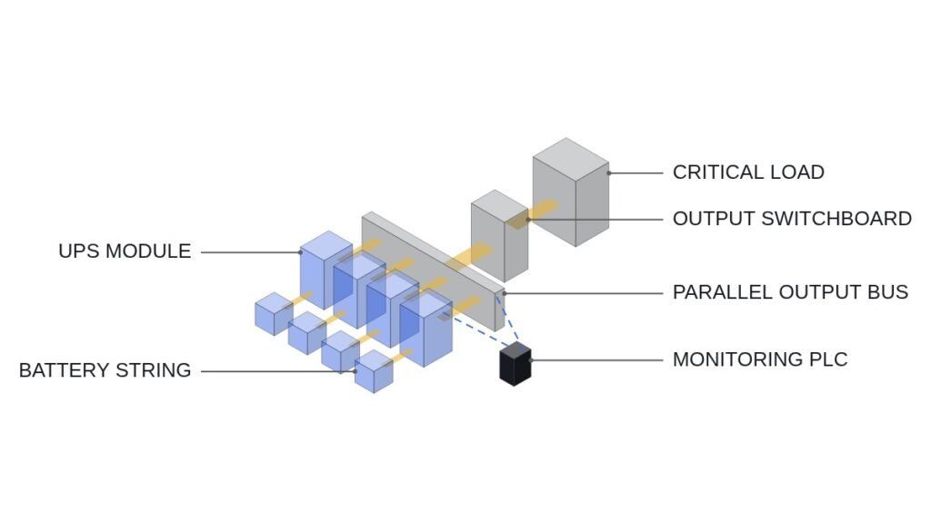
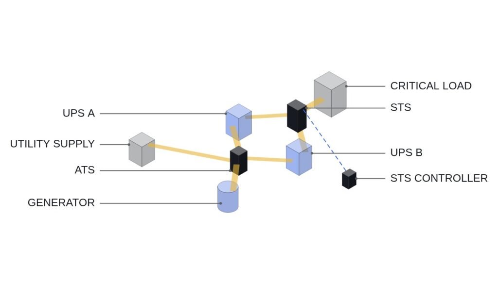
I will start with the conclusion. The criterion for selecting a data centre UPS is not capacity (kVA) but transfer time (ms), and whether the load survives that interval. According to IEA figures, battery-based UPS capacity additions in 2025 reached 45 GW, up 30% year on year. As that number has grown, the point where field practice most often goes wrong has also become clear: treating a 4 ms transfer time as “practically uninterrupted.”
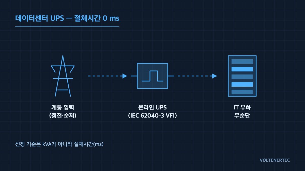
The hold-up time of a server SMPS is typically 10-20 ms. A 4 ms transfer passes on paper, but a 4 ms transfer that starts when the input voltage has already sagged is a different matter. This article sets out, circuit by circuit and step by step, where that margin disappears.
1. IEC 62040-3 classification: read the standard code, not the catalogue term
| Classification | Common name | Transfer time | Efficiency (normal) | Output frequency |
|---|---|---|---|---|
| VFI | Online double conversion | 0 ms | 94-97% Eco mode 98-99% |
Regenerated independently of input (fixed 50 Hz) |
| VI | Line interactive | 2-4 ms | 97-98% | Follows input frequency |
| VFD | Offline / standby | 4-10 ms | 97-98% | Passes input through as is |
Implication: Looking only at the efficiency column, VFD and VI appear better, but they are more efficient precisely because they pass the grid straight through in normal operation. In other words, the reason for their higher efficiency and the reason a transfer time exists are the same. For data centre loads, the value to write in the specification is VFI-SS-111; the last three digits are the performance classes for input voltage changes, output voltage transient behaviour, and response to non-linear loads respectively. If you specify capacity only and leave this code blank, VI products will slip in at the tender stage.
2. 45 GW is not just central UPS
This is the observation I most want to emphasise. If you picture all UPS additions as central UPS units in the electrical room, you miss how recent installations are configured. A substantial share is moving down into BBUs (Battery Backup Units) inside the server racks. The fact that a Korean cell maker presented high-power cells dedicated to data centre UPS and BBU as a separate line-up at InterBattery 2026 is part of the same trend.
From an electrical design standpoint, the two are completely different in character. A central UPS sits in series in the AC system and creates an event called transfer. A rack BBU is connected in parallel to the DC bus of the server power supply. In a parallel configuration, the transfer event does not exist at all. When the grid drops, current simply starts to flow in the diode’s direction the moment the bus voltage falls.
There is a price, though. When backup points are scattered across hundreds of racks, the number of battery status monitoring points also becomes hundreds. The approach used to manage the battery string of one central UPS cannot cope, and a configuration that collects each rack’s BMS communication to the upper level becomes essential. It is a structure that removes the transfer-time problem with circuitry, and takes on a monitoring problem through communication instead.
3. Backup time calculation: using nameplate Ah as is gives the wrong answer
The Ah on a battery nameplate is based on a specific hour rate (usually the 10-hour rate). A UPS discharges at a high rate of 5-15 minutes, so the actual usable capacity is lower. For lead-acid (VRLA) this is corrected with the Peukert exponent; for lithium-ion, with DoD, state-of-health and temperature derating.
# -*- coding: utf-8 -*-
"""
UPS battery backup time sizing
- VRLA: Peukert equation to reflect reduced effective capacity at high discharge rates
- LiB : DoD / SOH / temperature derating applied as multipliers
Units: voltage V, current A, power kW, time min
"""


def dc_current(load_kw: float, v_bus: float, eta_inv: float) -> float:
    """
    DC current [A] the battery string must actually deliver for a given load

    I_dc = (P_load / eta_inv) / V_bus
    - eta_inv : inverter efficiency (typically 0.92-0.96). The battery must supply the losses too
    - v_bus   : nominal battery string voltage [V] (number of cells x nominal cell voltage)
    """
    p_dc_w = (load_kw * 1000.0) / eta_inv      # required power at inverter input [W]
    return p_dc_w / v_bus


def vrla_backup_min(c_ah: float, hour_rate: float,
                    i_a: float, peukert_k: float = 1.25) -> float:
    """
    VRLA backup time [min] - Peukert equation

        t = H * ( C / (I * H) ) ** k

    - c_ah      : nameplate capacity [Ah]
    - hour_rate : nameplate hour rate H [h] (e.g. 10.0 for the 10-hour rate)
    - peukert_k : Peukert exponent. Typically 1.1-1.3 for VRLA; the penalty grows at higher rates
    Note that with k=1 the cell becomes ideal and the hour-rate concept disappears.
    """
    t_h = hour_rate * (c_ah / (i_a * hour_rate)) ** peukert_k
    return t_h * 60.0


def lib_backup_min(c_ah: float, i_a: float, dod: float = 0.90,
                   soh: float = 0.80, k_temp: float = 1.00) -> float:
    """
    Lithium-ion backup time [min]

        t = (C * DoD * SOH * k_temp) / I

    - dod    : upper limit of depth of discharge (0.85-0.95 for UPS use)
    - soh    : remaining capacity at end of life (EOL). Always design on an EOL basis
    - k_temp : temperature correction factor (1.00 at 25 deg C, 0.85-0.90 around 0 deg C)
    Lithium-ion loses little capacity at high discharge rates, so the Peukert correction is omitted;
    instead, the BMS low-voltage cutoff sets the actual end voltage, so the DoD limit dominates.
    """
    t_h = (c_ah * dod * soh * k_temp) / i_a
    return t_h * 60.0


if __name__ == "__main__":
    # Example: load 100 kW, battery bus 480 V, inverter efficiency 94%
    I = dc_current(load_kw=100.0, v_bus=480.0, eta_inv=0.94)
    print(f"Required DC current : {I:8.1f} A")

    # VRLA 500 Ah (10-hour rate) string
    print(f"VRLA backup time    : {vrla_backup_min(500.0, 10.0, I):8.1f} min")

    # LiB 200 Ah string, EOL 80% / DoD 90% / 25 deg C
    print(f"LiB  backup time    : {lib_backup_min(200.0, I):8.1f} min")
Implication: Even with the same nameplate capacity, VRLA loses a large share of its effective capacity at high discharge rates, while for lithium-ion the result is dominated by where you set the SOH (remaining capacity at end of life). A backup time calculated with an initial SOH of 100% is only correct on the day of commissioning. Set your design value on an EOL basis. The real figure must be verified against the battery manufacturer’s constant-power discharge table (W/cell); the code above is for first-pass sizing.
4. Safety interlock checklist: order of checks before start-up
In a UPS system, the battery side is always live even when the input is energised. Any sequence description starts with the interlocks.
- ☐ Is the EMO (emergency off) circuit built as a hardwired series circuit? A configuration that trips via a PLC output is not acceptable
- ☐ Is rectifier start-up physically blocked while the battery breaker (MCCB) is open?
- ☐ Is the make-before-break sequence mechanically enforced when the maintenance bypass is operated?
- ☐ Are the battery room high-temperature alarm (typically 35 deg C) and the ventilation fan run confirmation signal wired to inputs?
- ☐ Is the input phase-loss / phase-reversal monitoring relay contact wired in series in the rectifier start conditions?
- ☐ In parallel operation, is a load-sharing imbalance alarm threshold set?
Example I/O map
| Address | Signal | Operating condition |
|---|---|---|
X000 |
EMO_NC | NC contact. When open, all outputs forced OFF. No logic bypass |
X001 |
MAIN_PWR_OK | ON when input voltage and frequency are normal (e.g. 380 V ±10%, 50 Hz ±1%) |
X002 |
BAT_CB_CLOSED | Battery breaker closed confirmation. If OFF, rectifier start is blocked |
X003 |
BAT_TEMP_HI | ON when battery room temperature exceeds the upper limit → charge current limited |
X004 |
VENT_FAN_RUN | Ventilation fan run confirmation. If OFF persists, charge-stop interlock |
Y000 |
RECT_START | ON only when X000, X001 and X002 are all satisfied |
Y010 |
BYPASS_CMD | Static bypass transfer command on inverter fault or overload |
Y020 |
ALM_LAMP | Alarm indication. Self-latching; reset by manual operation only |
Implication: X000 is included in the conditions for Y000, but that is for indication and monitoring, not a safety function. The actual EMO trip must happen in a hardwired path where the contact directly breaks the main circuit. The moment you depend on the PLC scan time (a few ms to tens of ms), the requirements for a safety circuit are no longer met.
5. Boundary conditions: VFI is not always the answer
The conclusion above assumes a load of SMPS-based IT equipment and an unstable grid. The judgement changes in the following cases.
- Sites with stable grid quality and very short annual outage time — the constant conversion loss of continuous VFI operation (3-6%) may exceed the benefit during outages. This is the range where eco mode or VI is a rational choice
- Loads that are not servers but equipment with high tolerance to transfer time, such as motors and lighting — VFD is sufficient
- New data centres where rack BBUs are already fully deployed — double investment in a VFI central UPS duplicates the backup layer
If only one selection criterion is kept, it is this: how many ms is the hold-up time of the load’s power supply? If the transfer time is shorter than this value with a margin of at least 2x, you can step down to VI; otherwise, VFI.
Field checkpoints
- Do not write only the capacity (kVA) in the specification; state the IEC 62040-3 performance code (e.g. VFI-SS-111)
- Size backup time on an EOL SOH basis. If you size on commissioning values, you will fall short three years later
- Measure the hold-up time of the load-side SMPS. Catalogue values and measured values often differ — requires waveform analysis and field measurement