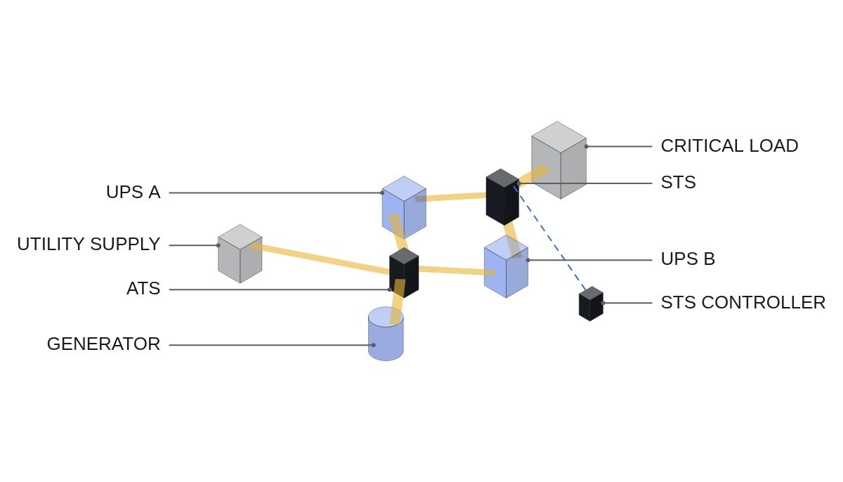
Bottom line first. Choosing between an ATS and an STS does not end with comparing transfer speed. An ATS changes the source through mechanical contacts and assumes an interruption; an STS uses thyristors (SCRs) to move between two live, synchronized sources. So the decision rests on two questions: are the two sources synchronized, and can transfer be blocked during a downstream fault? Between unsynchronized sources such as utility and generator, use an ATS; between two synchronized UPS systems, use an STS. For the STS, where it sits — ahead of or behind the transformer — matters as much as the choice itself.
Safety interlocks first — checking order for each transfer device
Transfer switch interlocks come down to two things: the two sources are never paralleled unintentionally, and a fault is never moved onto a healthy source. The first is enforced mechanically and by hardwiring; the second by transfer-inhibit logic.
- EMO is hardwired directly into the source-side trip circuits on both sides of the transfer device. The PLC and the transfer controller receive EMO status only as a monitoring input.
- In an open-transition ATS, simultaneous closing of the utility and generator contacts is blocked by two layers: a mechanical interlock and an electrical interlock (the other side’s 52b in series). Neither one is relied on alone.
- A closed-transition ATS briefly parallels the two sources, so it needs a synchronism check (25) and a limit on the paralleling time. Paralleling a generator with the grid is subject to agreement with the system operator, so it is an item to verify before the specification is fixed.
- An STS inhibits transfer when it detects downstream overcurrent (fault current). Transferring during a fault moves the fault onto the healthy source and loses both systems.
- If the phase difference between the STS sources leaves the permitted window, transfer is inhibited immediately or, depending on the manufacturer setting, switched to a delayed transfer (an intentional dead band).
- If the generator is a separately derived system with its own neutral bond, use 4-pole switching so the neutral is transferred as well. With 3 poles, neutral current splits across two paths and ground-fault relays may misoperate or fail to operate.
The two devices on a time chart
An ATS transfer is the sum of several set times. Where the preconditions are not given, they are defined against the time chart below.
- t0: utility abnormality detected (undervoltage, phase loss or frequency excursion elements).
- t0 + T1: confirmation delay, a filter so that a momentary voltage dip does not start the generator.
- Start signal → cranking → rated speed → voltage and frequency established (T2).
- Utility side opens → neutral delay (T3, for decay of motor residual voltage) → generator side closes.
- On utility return, retransfer after a return delay (T4), then generator cool-down run.
The interruption is T1 + T2 + T3, measured in seconds. That is why there is a UPS downstream of the ATS. An ATS is not an uninterruptible device; it is a device that changes the source.
An STS works differently. It judges a preferred-source voltage excursion within a few ms, removes the gate signal from the preferred-side SCRs, then gates the alternate-side SCRs. The key point is that an SCR keeps conducting until current zero even after its gate is removed. If SCRs on both sources conduct at once, the two sources are short-circuited, so the logic that confirms turn-off on the preferred side is the heart of STS control. Product specifications generally quote transfer times in the 1/4 to 1/2 cycle range; at 60 Hz, a quarter cycle is about 4.2 ms and a half cycle about 8.3 ms.
STS placement — ahead of or behind the transformer
This is the part of the article I most want to stress. Placing the STS on the transformer primary reduces the number of STS units and transformers. But transferring with a phase difference leaves the residual flux in the downstream transformer core out of step with the new voltage, creating a DC offset and an inrush current. That inrush can trip the STS’s own overcurrent detection and inhibit transfer, or trip the upstream breaker.
Placing the STS on the transformer secondary (for example at the PDU output) needs one transformer per source, so equipment increases, but the transfer never re-energizes a transformer and the problem disappears. Manufacturers offer inrush-limiting transfer techniques, but their actual effect with a given transformer and load requires waveform analysis and field measurement. A configuration that keeps the phase difference between the two sources small is the precondition for primary-side placement.
ATS transfer sequence (ST pseudocode)
(* I/O MAP *)
(* %I0.0 DI_EMO_CHAIN_OK    : EMO hardwired chain healthy - status monitoring only *)
(* %I0.1 DI_UTIL_V_OK       : utility voltage elements (27/59/81) healthy contact *)
(* %I0.2 DI_GEN_V_OK        : generator voltage and frequency established *)
(* %I0.3 DI_CB_UTIL_CLOSED  : utility-side breaker 52a *)
(* %I0.4 DI_CB_GEN_CLOSED   : generator-side breaker 52a *)
(* %I0.5 DI_LOAD_FAULT      : downstream overcurrent relay (50/51) operated *)
(* %Q0.0 DO_GEN_START       : generator start command *)
(* %Q0.1 DO_CB_UTIL_OPEN    : utility-side open command *)
(* %Q0.2 DO_CB_GEN_CLOSE    : generator-side close command - after hardwired 52b interlock *)
(* the mechanical interlock physically prevents simultaneous closing regardless of code *)

CASE I_STEP OF
  0: (* on utility, standby *)
     TON_CONFIRM(IN := NOT DI_UTIL_V_OK, PT := T#3S);   (* T1 confirmation delay - example *)
     IF TON_CONFIRM.Q THEN I_STEP := 10; END_IF;

  10: (* start generator *)
     DO_GEN_START := TRUE;
     IF DI_GEN_V_OK THEN I_STEP := 20; END_IF;

  20: (* no transfer during a fault *)
     IF DI_LOAD_FAULT THEN
        X_TRANSFER_BLOCKED := TRUE;          (* alarm, wait for manual reset *)
     ELSE
        DO_CB_UTIL_OPEN := TRUE;
        IF NOT DI_CB_UTIL_CLOSED THEN I_STEP := 30; END_IF;
     END_IF;

  30: (* neutral delay T3 - motor residual voltage decay *)
     TON_NEUTRAL(IN := TRUE, PT := T#1S);    (* example *)
     IF TON_NEUTRAL.Q AND NOT DI_CB_UTIL_CLOSED AND DI_EMO_CHAIN_OK THEN
        DO_CB_GEN_CLOSE := TRUE;
        I_STEP := 40;
     END_IF;

  40: (* on generator - watch for utility return *)
     TON_RETURN(IN := DI_UTIL_V_OK, PT := T#300S);   (* T4 return delay - example *)
     IF TON_RETURN.Q THEN I_STEP := 50; END_IF;       (* 50 onward: retransfer, cool-down *)
END_CASE;
All timer values are illustrative. Even with conditions in the code, DO_CB_GEN_CLOSE still needs a separate hardwired interlock: the utility-side 52b contact in series in the closing coil circuit. The code condition is a second layer on top of that.
ATS versus STS
| Item | ATS | STS |
|---|---|---|
| Switching element | Mechanical contacts | SCR (thyristor) |
| Gap during transfer | Yes (open transition, seconds) | A few ms (synchronized) |
| Source condition | Unsynchronized allowed | Synchronism required |
| Fault current | Handled by breakers | Limited SCR rating, transfer inhibit |
| Standing loss | Contact resistance level | SCR conduction loss, cooling |
| Standards | IEC 60947-6-1, UL 1008 | IEC 62310 series |
| Typical location | Utility–generator | Between synchronized UPS A/B |
The “gap during transfer” row makes the STS look like the winner, but that value is valid only when the “source condition” row holds. Put an STS between utility and generator and, for as long as the sources are unsynchronized, it runs in transfer-inhibit or delayed-transfer mode, ending up with a gap similar to an ATS plus the standing SCR losses. STS speed is not a property of the device; it is a property of the source configuration.
Selection and commissioning checklist
- □ Has the single-line diagram confirmed that the two sources are always synchronized (including where the sync reference comes from)?
- □ If the STS is on the transformer primary, is an inrush test for out-of-phase transfer in the commissioning items?
- □ Has transfer inhibit on a downstream fault been verified with a simulated signal?
- □ Were the ATS mechanical and electrical interlocks tested separately?
- □ Was 3-pole or 4-pole chosen to match the generator neutral grounding?
- □ Were the ATS confirmation, neutral and return delays checked against the load characteristics (motor residual voltage and so on)?
- □ Is the STS maintenance bypass key interlock sequence posted on a nameplate?
Boundary conditions — where this choice goes wrong
The case for an STS holds only when both sources come from the same upstream supply or are locked in phase by inter-UPS synchronization control. If there is an operating mode where the sync reference disappears — for example, the two UPS systems running on separate generators — the STS stays in transfer inhibit in that mode. Check first how often and for how long that mode occurs.
Conversely, the case that an ATS is sufficient holds only when a downstream UPS absorbs the multi-second gap. If sensitive loads are fed by an ATS without a UPS, the transfer gap is a load outage.
The single decision rule: if the two sources are synchronized in every operating mode and transfer inhibit on a downstream fault is guaranteed, use an STS; otherwise use an ATS with a downstream UPS.