The bottom line first. A solid-state transformer (SST) is a net loss in most cases when evaluated as a straight replacement for a conventional oil-filled transformer. Efficiency, lifespan, and track record still favor the conventional unit. There is exactly one configuration where SST wins: where the load requires a power-conversion device (PCS) or rectifier bolted on right after the transformer anyway. The question to ask is whether the transformer and the converter can be merged into one — if that condition doesn’t hold, SST is not even a candidate.
1. What’s happening right now
Heron Power, founded by a former Tesla executive, announced it is building a 40 GW/year power-conversion-device manufacturing plant in California. Around the same time, Siemens Energy said its gas-turbine order backlog has swelled to 70 GW with lead times running past three years, and it will expand transformer manufacturing capacity by 50% by 2030.
The two announcements are two sides of the same coin. Grid infrastructure investment is falling short, and data centers are pushing straight into the project schedule regardless. The primary reason semiconductor-based converters are drawing attention is not performance — it’s that their manufacturing process runs closer to the semiconductor line, giving them faster ramp-up speed.
2. Structural difference — the 60 Hz iron core disappears
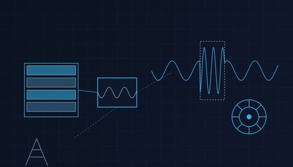
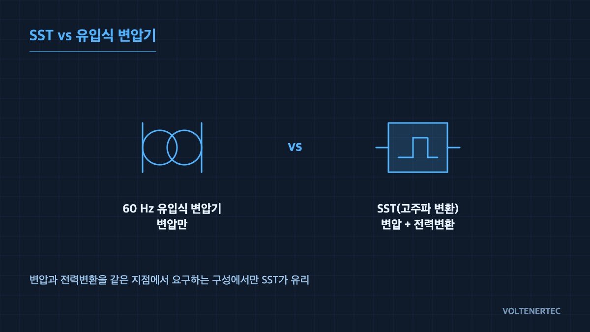
A conventional transformer runs the 60 Hz line frequency directly, so its core cross-section scales up in inverse proportion to frequency. SST switches the medium voltage through semiconductors into a high-frequency link of several kHz to several tens of kHz, then passes it through an isolation transformer. At the same power rating the core volume shrinks dramatically, and a DC link naturally appears at the intermediate stage.
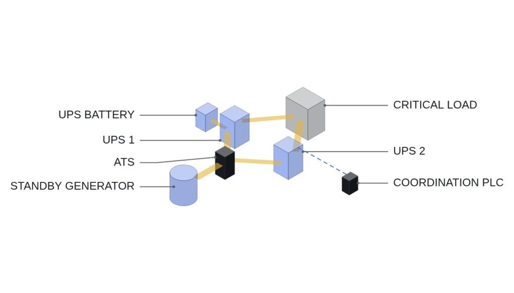
What matters in practice is not the reduced footprint but that DC link. Data-center ESS is moving toward a medium-voltage-UPS-integrated DC-bus architecture, where one of the stages that used to run AC-transform → rectify → DC-bus collapses into a single pass. The US’s 1.1 GW-class data-center-connected BESS project adopting an expanded DC architecture reads as the same trend.
3. Comparison table — from a medium-voltage-conversion perspective
| Item | Conventional transformer + separate PCS | Solid-State Transformer (SST) |
|---|---|---|
| Conversion method | 60 Hz iron core, passive device | Several kHz–tens of kHz high-frequency link, active device |
| Standalone efficiency | 99%+ (transformer, load-dependent) | 96–98% level (multi-stage conversion) |
| System-level efficiency | Sum of transformer + rectifier/PCS losses | Reversible via stage integration |
| Footprint / weight | Large and heavy, needs foundation/soundproofing | Dramatic reduction, more site-layout freedom |
| Fault-current contribution | Large-value contribution, following impedance | Limited by device protection (suppressed within a few ms) |
| Protection coordination | Existing overcurrent coordination holds as-is | Requires coordination redesign — trip current is too small |
| Voltage / reactive-power control | Tap switching (discrete, seconds-scale) | Continuous control (ms-scale), harmonic compensation possible |
| Failure mode | Insulation degradation / winding short (progressive, predictable) | Device / gate-drive failure (abrupt) |
| Operating track record | Decades, 30-year lifespan assumed | Still accumulating, long-term reliability data lacking |
| Lead time | Extended out to 2–4 years | Relatively favorable once a production line is secured |
The row deserving the most attention in this table is not efficiency — it’s fault-current contribution. SST limits current within a few milliseconds to protect its own devices. Existing grid protection has its 51/50 relay settings locked in on the premise that “a sufficiently large fault current flows” — the moment SST is inserted, that premise disappears. It’s not the equipment that changes; it’s the protection philosophy.
4. Deployment review checklist
- Check for downstream duplication — is there already a rectifier/PCS after the transformer? If not, most of SST’s advantage disappears.
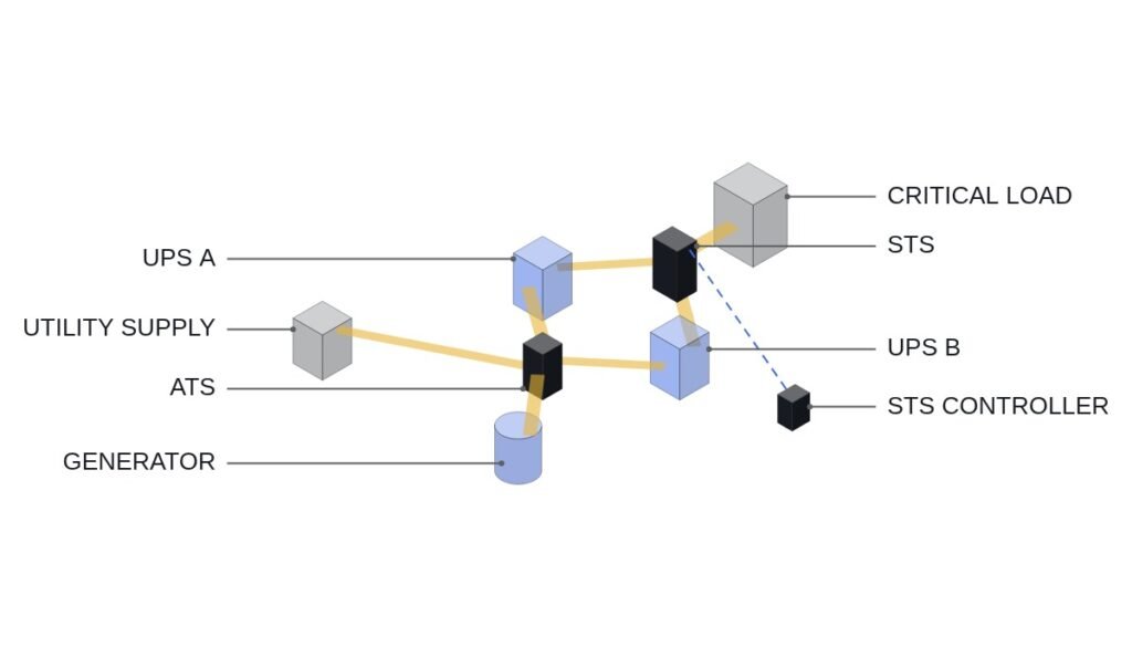
- Re-review protection coordination — under a limited fault-current condition, confirm the downstream breaker’s 51/50 settings still coordinate. If needed, combine with communication-based coordination (zone interlocking, logic selectivity) rather than current-based alone.
- DC-side protection — a DC-bus configuration requires arc detection and DC fault-clearing means as separate line items. The AC-breaker logic cannot simply be carried over.
- Harmonics / EMC — reflect high-frequency switching noise’s grounding path and cable-shield treatment in the early layout. Field noise stays as a waveform-analysis-and-measurement item.
- Cooling dependency — for SST, a cooling failure is an immediate shutdown. Include the cooling system in the safety-interlock signal, and define the sequence as detect-on-over-temperature → shutdown.
- Abnormal-stop circuit — EMO and upper-level protection trips keep a hardwired path. They are not replaced by control-software judgment.
- Spares and maintenance system — a conventional unit is maintained predictively via dissolved-gas analysis (DGA), while SST is module-replacement-only. Build spare-module inventory and replacement time into the contract terms.
- Standards conformance — confirm by documentation which IEC test-series regulation the type test was carried out under. A mere “equivalent performance” claim is not sufficient grounds for acceptance.
5. Boundary condition — where SST becomes disadvantageous
Where the load is simply AC and requires no conversion stage, and where the plant premise assumes 25+ years of maintenance-free operation, SST’s advantage disappears. Active devices fail at a higher rate than passive devices, and failure is abrupt. Unlike a conventional transformer whose insulation degradation is predictable over years, semiconductor modules stop without warning. On sites where maintenance staffing isn’t robust, this gap dominates availability.
The selection criterion comes down to one thing: evaluate SST only at a grid point that requires both voltage transformation and power conversion, and only at a site where maintenance access is feasible. If either of the two doesn’t hold, a conventional transformer plus separate PCS is still the right answer. Crossing this line purely because lead time is short simply defers the cost — from deployment timing straight into protection-coordination redesign and maintenance-system buildout.
References
- Heron Power, building a 40 GW/year power-conversion manufacturing plant — Energy-Storage.news
- Siemens Energy gas-turbine backlog, 50% transformer capacity expansion — Utility Dive
- 1.1 GW data-center-connected BESS, first-stage delivery — GlobeNewswire