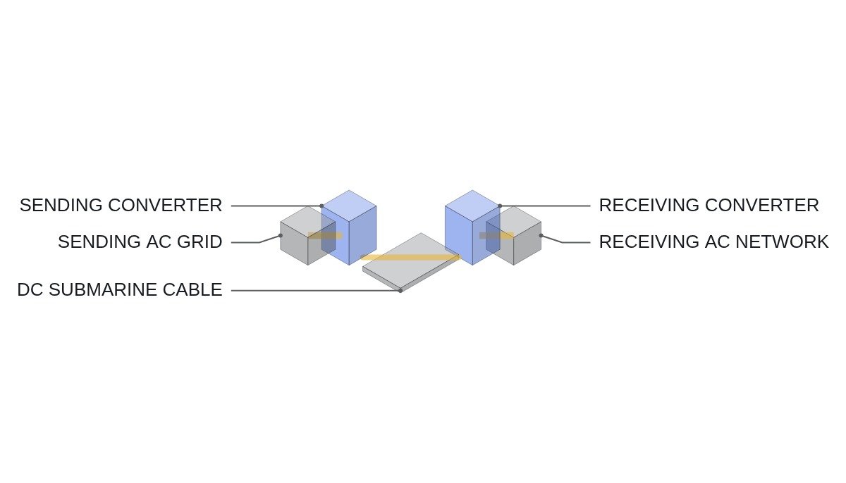
Bottom line first. If the HVDC versus HVAC choice is seen only as a break-even distance — “HVDC is cheaper beyond so many km” — you miss the place where the decision flips first. On overhead routes the distance logic works, but when there is a submarine or underground cable section, AC charging current sets a limit before distance does. And once HVDC is chosen, the next branch is decided by the strength of the AC network at the connection point. A weak or passive network points to a voltage-source converter (VSC); a strong network with a long, high-capacity overhead line favours a line-commutated converter (LCC).
Safety interlocks first — converter station access and pole start conditions
An HVDC converter station stores energy on the AC side, the DC side, in the valves and in the filter banks. The starting point of the interlock is to enforce, through a mechanical key sequence, that people enter only after every energy source has been isolated and earthed.
- EMO and converter emergency stop are hardwired directly to the AC breaker trip circuits and to valve gate blocking. Higher-level control and the PLC only monitor status.
- Valve hall entry follows “open AC breakers → block valves → confirm DC voltage gone → close DC pole and neutral earthing switches → release door key”, enforced by key interlock.
- AC filter and capacitor banks are approached only after opening, the discharge time and earthing.
- DC earthing switches carry a voltage-detection condition so they cannot close while DC voltage remains.
- Valve cooling abnormalities (flow, conductivity) must never be left out of the operating permissives.
- On loss of communication with the remote station, pole behaviour converges to a predefined state. It is not left holding the last command.
Charging current on the cable section
An AC cable is a capacitor between conductor and screen. Even in steady state a charging current proportional to route length flows, carrying no active power while occupying the conductor’s thermal capacity.
- Assumption: 345 kV, 60 Hz, cable capacitance 0.2 µF/km (varies with cable specification).
- Phase voltage = 345 / √3 ≈ 199.2 kV, ω = 2π × 60 ≈ 377 rad/s.
- Charging current per km = 199.2 kV × 377 × 0.2 µF ≈ 15.0 A/km.
- Charging reactive power per km = V² × ωC = (345 kV)² × 377 × 0.2 µF ≈ 9.0 Mvar/km.
- Fed from one end only: about 750 A at 50 km, about 1,500 A at 100 km.
Assuming a conductor rating of 1,000 A, charging current alone uses up the rating at about 67 km when fed from one end. Shunt reactors at both ends extend that distance, but no compensation can be placed in the middle of a submarine section. DC has no charging current in steady state, so this limit does not exist. Overhead lines have far less capacitance than cable, pushing the same problem out to hundreds of km. This is why commonly quoted break-even distances differ — hundreds of km for overhead lines, tens of km for cable — and the actual value depends on project cost conditions, making it an item to verify.
LCC versus VSC — the second branch, decided by the connection point
An LCC is a thyristor converter that relies on AC network voltage to commutate current. The AC network at the connection point must therefore be strong enough, and because conversion consumes reactive power, AC filters and capacitor banks take up a large area. In return, on a DC line fault it can suppress fault current by firing-angle control and restart, which is an operating advantage on long overhead routes with frequent lightning.
A VSC builds its own voltage with self-commutated devices, so it can connect to weak or passive networks (offshore wind, islands) and controls reactive power independently. On the other hand, in a half-bridge MMC, a DC-side short keeps being fed from the AC side through the anti-parallel diodes, so the converter alone cannot interrupt fault current and an AC breaker trip is required. For a VSC with a long overhead section this bears directly on availability, and whether to adopt full-bridge cells or DC breakers becomes a design variable.
VSC pole start permissive (ST pseudocode)
(* I/O MAP - VSC converter station, one pole *)
(* %I4.0  DI_EMO_CHAIN_OK      : EMO hardwired chain healthy - status monitoring only *)
(* %I4.1  DI_VALVE_HALL_LOCKED : valve hall door key interlock locked *)
(* %I4.2  DI_DC_ES_OPEN        : DC pole earthing switch open *)
(* %I4.3  DI_COOL_OK           : valve cooling flow and conductivity normal *)
(* %I4.4  DI_AC_CB_CLOSED      : AC-side breaker 52a *)
(* %I4.5  DI_PREINS_R_BYPASSED : pre-insertion resistor bypassed *)
(* %I4.6  DI_REMOTE_READY      : remote station ready - received over comms *)
(* %IW300 AI_UDC_KV            : DC pole voltage kV *)
(* %Q4.0  DO_PREINS_BYPASS_CMD : pre-insertion resistor bypass command *)
(* %Q4.1  DO_DEBLOCK_PERMIT    : converter deblock permit *)
(* inter-station comms : IEC61850_GOOSE ready and trip signals *)

(* 1. AC breaker closed - cell capacitors charge through pre-insertion resistor *)
(*    bypass the resistor once DC voltage reaches a set fraction of target *)
IF DI_AC_CB_CLOSED AND (AI_UDC_KV >= R_UDC_PREINS_TH) THEN
    DO_PREINS_BYPASS_CMD := TRUE;      (* R_UDC_PREINS_TH is a manufacturer value *)
END_IF;

(* 2. deblock permit - safety, cooling, charging and remote readiness all hold *)
B_DEBLOCK_OK := DI_EMO_CHAIN_OK AND DI_VALVE_HALL_LOCKED AND DI_DC_ES_OPEN
                AND DI_COOL_OK AND DI_PREINS_R_BYPASSED AND DI_REMOTE_READY;

(* 3. remote ready lost - remove permit after delay, never hold last state *)
TON_LINK(IN := NOT DI_REMOTE_READY, PT := T#500MS);   (* example *)
IF TON_LINK.Q THEN B_DEBLOCK_OK := FALSE; END_IF;

DO_DEBLOCK_PERMIT := B_DEBLOCK_OK;
The pre-insertion resistor bypass voltage and the 500 ms communication-loss delay are illustrative; actual values follow the converter manufacturer’s design. Whether to block the pole immediately on communication loss, or to ramp power down along a defined trajectory first, is a matter for agreement with the system operator.
HVAC, LCC and VSC compared
| Item | HVAC | LCC | VSC |
|---|---|---|---|
| Long cable | Limited by charging current | No limit | No limit |
| Connection point | Not applicable | Strong network needed | Weak or passive OK |
| Reactive power | Line generates/absorbs | Converter consumes | Independent control |
| DC line fault | Not applicable | Suppressed by firing angle | Half-bridge needs AC trip |
| Station footprint | Substation scale | Large due to filters | Relatively small |
| Standards | General AC substation standards | IEC 60919 | IEC 62501 |
Read top to bottom, the table is the decision order. In the first row, if the cable section exceeds the charging-current limit, HVAC drops out; the second row, connection-point strength, splits LCC and VSC; the fourth row, the share of overhead line, decides the VSC cell type and DC fault measures. Distance and cost are compared only among the candidates that pass these three rows.
Boundary conditions — where distance logic comes back
If the cable section is short, most of the route is overhead, and load has to be tapped at intermediate substations, HVAC wins. AC branches with a single transformer; DC needs a converter station at every branch. When the route distributes power to several points rather than running point to point, the number of taps decides before the break-even distance does.
Also, when both ends sit inside the same synchronous network, HVDC offers control of power flow between the two points, but coordinating flow sharing with parallel AC lines becomes a new operating task. That operating condition is an item to confirm by system study.
The single decision rule: if the cable section’s charging current takes a substantial share of the conductor rating, or the connection point is passive or weak, choose HVDC; if the route is mainly overhead and needs intermediate taps, choose HVAC.