Bottom line first. The conditions for paralleling transformers are usually summarized as vector group (phase displacement) and polarity, voltage ratio (tap), and percent impedance, but these three are different in kind. The first two, when wrong, show up at closing as a large circulating current, so they are discrete conditions that can be blocked by an interlock before closing. A percent-impedance mismatch raises no alarm after closing; it quietly skews load sharing and trims the combined capacity of the two units. Parallel operation therefore needs a calculated “usable parallel capacity” managed as a load ceiling, separately from the interlocks.
Safety interlocks first — bus-tie breaker closing conditions
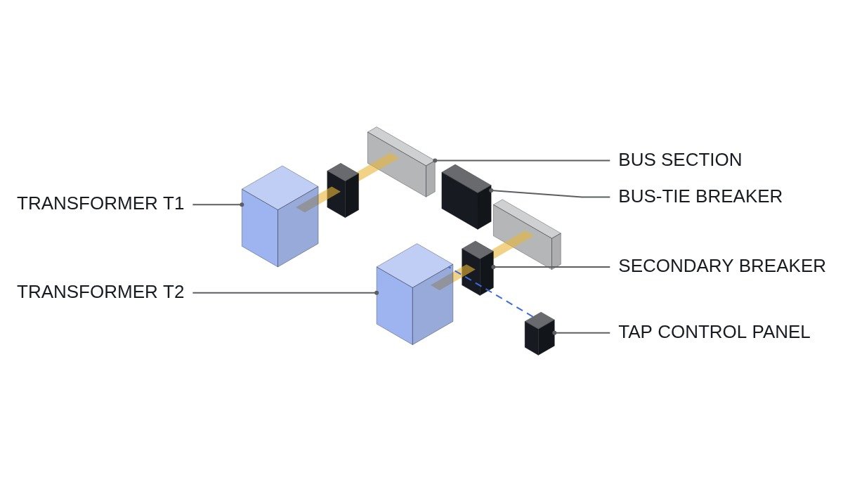
The point where two transformers are paralleled is usually the secondary bus-tie breaker. The close permissive and the trip linking during parallel operation have to be defined together.
- EMO is hardwired directly into the switchgear breaker trip circuits; the PLC only monitors status.
- Transformers with different vector groups are excluded from paralleling at the design stage. This condition does not change in operation, so it is fixed by checking the single-line diagram against nameplates, not by logic.
- If the two transformer primaries are fed from different incoming supplies, the bus-tie breaker gets a synchronism check (25) condition.
- With OLTCs, closing is permitted only when both tap positions match.
- If one transformer’s primary breaker trips during parallel operation, that transformer’s secondary breaker is inter-tripped. Otherwise the healthy transformer back-energizes the tripped unit from the secondary side, leaving it live even with its primary open. This is directly tied to worker safety.
- With the earthing switch closed or the lockout (86) not reset, the closing circuit is blocked by hardwiring.
How impedance mismatch trims combined capacity
Load sharing between paralleled transformers is proportional to rated capacity divided by percent impedance. The share of transformer i is S_i = S_L × (S_ir / Z_i) / Σ(S_jr / Z_j).
- Assumption: T1 1,000 kVA, 5 % impedance; T2 1,000 kVA, 6 % impedance; equal X/R ratios.
- Weights: T1 = 1000 / 5 = 200, T2 = 1000 / 6 ≈ 166.7. T1 share = 200 / 366.7 ≈ 54.5 %.
- At a 2,000 kVA load, T1 carries about 1,091 kVA (109 % of rating) and T2 about 909 kVA.
- Maximum load with neither unit overloaded = 1,000 / 0.545 ≈ 1,833 kVA, about 92 % of the combined 2,000 kVA rating.
Two units of identical nameplate rating, paralleled, and about 8 % of the combined capacity cannot be used. This loss raises no alarm; it first shows up as temperature in the lower-impedance transformer during summer load peaks. If X/R ratios also differ, active and reactive power shares differ from each other too, so accurate values require entering the resistive and reactive parts of both transformers separately.
Tap mismatch and circulating current
If the two voltage ratios differ, a circulating current flows between the transformers even at no load. For equal ratings, its magnitude is roughly the voltage difference (%) divided by the sum of the two percent impedances.
- Assumption: one tap step difference = 1.25 %, impedances 5 % + 6 %.
- Circulating current ≈ 1.25 / (5 + 6) ≈ 0.114, so about 11 % of rated current flows regardless of load.
This current is mostly reactive and hard to see on an energy meter, but it raises winding copper loss and temperature and eats into one unit’s margin. If each OLTC runs its own automatic voltage control, the two controllers can drive taps in opposite directions, so during parallel operation they are normally tied in a master-follower arrangement.
Parallel closing and tap synchronization logic (ST pseudocode)
(* I/O MAP *)
(* %I5.0  DI_EMO_CHAIN_OK    : EMO hardwired chain healthy - status monitoring only *)
(* %I5.1  DI_T1_HV_CB_CLOSED : T1 primary breaker 52a *)
(* %I5.2  DI_T2_HV_CB_CLOSED : T2 primary breaker 52a *)
(* %I5.3  DI_SYNC_CHECK_OK   : synchronism check relay 25 permit contact *)
(* %I5.4  DI_LOR_86_RESET    : lockout 86 reset *)
(* %I5.5  DI_ES_OPEN         : bus earthing switch open *)
(* %IW400 AI_T1_TAP_POS      : T1 tap position - transducer *)
(* %IW401 AI_T2_TAP_POS      : T2 tap position - transducer *)
(* %Q5.0  DO_TIE_CLOSE_PERMIT: bus-tie close permit - in series after hardwired conditions *)
(* %Q5.1  DO_T2_TAP_RAISE    : T2 OLTC raise - follower *)
(* %Q5.2  DO_T2_TAP_LOWER    : T2 OLTC lower - follower *)
(* %Q5.3  DO_TAP_MISMATCH_ALM: tap mismatch alarm, OLTC auto stopped *)
(* secondary inter-trip on primary breaker trip is hardwired in the protection circuit *)

I_TAP_DIFF := AI_T1_TAP_POS - AI_T2_TAP_POS;

(* 1. close permit - taps equal, both primaries closed, in sync, 86 reset, earthing switch open *)
DO_TIE_CLOSE_PERMIT := DI_EMO_CHAIN_OK AND DI_T1_HV_CB_CLOSED AND DI_T2_HV_CB_CLOSED
                       AND DI_SYNC_CHECK_OK AND DI_LOR_86_RESET AND DI_ES_OPEN
                       AND (I_TAP_DIFF = 0);

(* 2. master-follower - T1 is master, T2 follows one step at a time *)
TON_STEP(IN := (I_TAP_DIFF <> 0) AND NOT X_TAP_BLOCK, PT := T#5S);   (* tap step interval - example *)
DO_T2_TAP_RAISE := TON_STEP.Q AND (I_TAP_DIFF > 0);
DO_T2_TAP_LOWER := TON_STEP.Q AND (I_TAP_DIFF < 0);

(* 3. follow failure - mismatch lasting 30 s or more stops OLTC auto and alarms *)
TON_MISMATCH(IN := I_TAP_DIFF <> 0, PT := T#30S);                     (* example *)
IF TON_MISMATCH.Q THEN
    X_TAP_BLOCK := TRUE;            (* no automatic tap action until manual reset *)
END_IF;
DO_TAP_MISMATCH_ALM := X_TAP_BLOCK;
The 5 s step interval and 30 s mismatch time are examples and must be longer than one OLTC mechanism step. Tap position transducer error or contact chatter can create false mismatches, so the local tap indication and the PLC input should be compared first. There is deliberately no logic that opens the bus-tie breaker automatically on mismatch, because breaking the parallel can overload one transformer; that decision is left to the operator.
Paralleling conditions at a glance
| Condition | If mismatched | How to manage |
|---|---|---|
| Vector group, polarity | Large circulating current, effectively a short | Excluded at design |
| Phase rotation | Short circuit on closing | Phase rotation test |
| Voltage ratio (tap) | No-load circulating current | Tap-equal interlock, master-follower |
| Percent impedance | Uneven sharing, lost capacity | Load ceiling from usable parallel capacity |
| X/R ratio | Different P and Q sharing | Compare manufacturing specs |
| Rating ratio | Smaller unit tends to overload | Manufacturer and IEC 60076-8 review |
The top three rows ask “may we close?”; the bottom three ask “after closing, how far can we load it?” Interlocks cover only the top three. The bottom three are not managed unless a calculated load ceiling is entered into the monitoring system.
Pre-paralleling checklist
- □ Have vector group, rated voltage, tap range and step size of both transformers been checked against nameplates and test reports?
- □ Was a phase rotation test done before the first bus-tie closing?
- □ Has usable parallel capacity been calculated from impedance and X/R, with a load ceiling alarm set?
- □ Has the downstream breaker interrupting rating been reviewed for the increase in secondary fault current when paralleled?
- □ Has the secondary inter-trip on a primary breaker trip been verified by an actual test?
- □ Have OLTC master-follower changeover and the mismatch alarm been tested?
The fault-current item is easy to overlook. Assumption: 22.9 kV/380 V, 1,000 kVA, source impedance neglected. Rated secondary current = 1,000 kVA / (√3 × 380 V) ≈ 1,519 A; with 5 % impedance the fault current is about 30.4 kA, and with 6 % about 25.3 kA. Paralleled, the secondary bus fault current totals about 55.7 kA, which can exceed the interrupting rating of breakers selected for single-unit operation.
Boundary conditions — where paralleling is the worse choice
The benefits of parallel operation are keeping the load live through one unit’s failure and running one unit alone at light load. But as the calculation above shows, paralleling raises the secondary fault current and may require stronger downstream breakers and busbars. If that cost is high and the load can tolerate a few seconds of interruption for a manual or automatic transfer when one unit fails, it is better to split the bus, run the units separately and keep the bus-tie normally open for automatic transfer.
Conversely, if the load cannot tolerate even a momentary interruption, interrupting margin is already in place, and the pair matches on impedance and tap conditions, continuous parallel operation wins.
The single decision rule: if the paralleled secondary fault current stays within the existing breaker interrupting rating and the load cannot tolerate a momentary interruption, run in continuous parallel; if either fails, use a normally open bus-tie with automatic transfer.