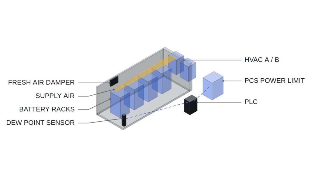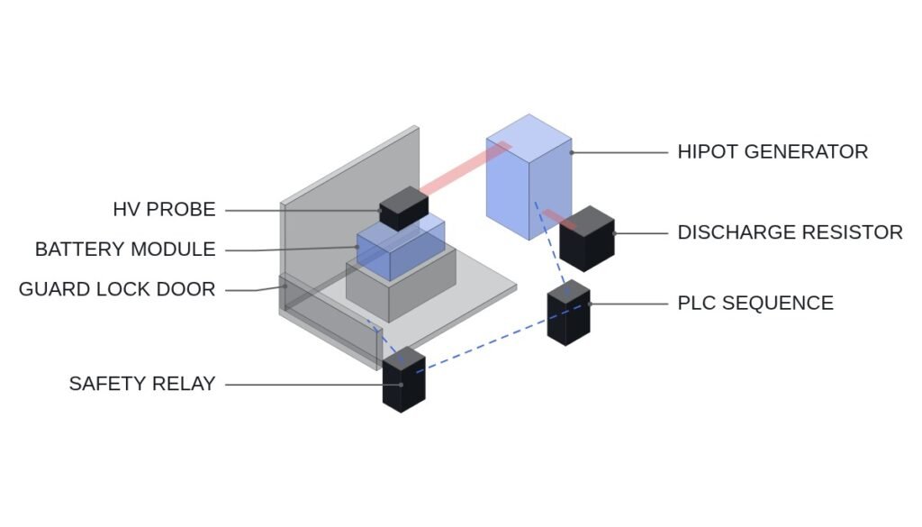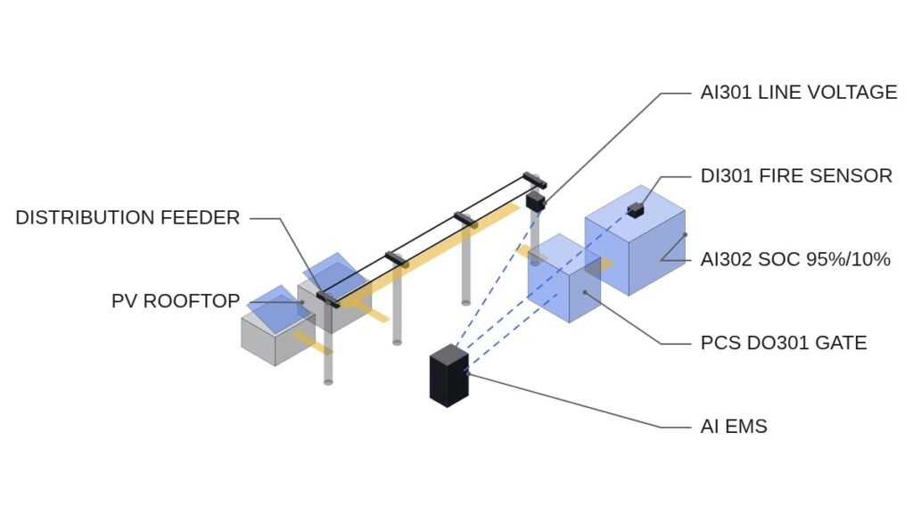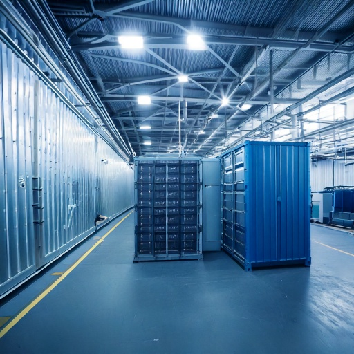
An ESS (Energy Storage System) is made up of battery racks built from stacked battery cells, a PCS (Power Conversion System) that converts between DC and AC, a BMS (Battery Management System) that monitors and protects the battery in real time, and an EMS (Energy Management System) that controls the whole installation.
| Component | Role |
|---|---|
| Battery rack | Combines battery modules in series and parallel to reach the required voltage and capacity |
| BMS | Monitors cell voltage, temperature and SOC; protects against overcharge, over-discharge and overheating |
| PCS | Converts power between the battery (DC) and the grid (AC); controls charge and discharge |
| EMS | Combines PCS, BMS and grid data to decide charge/discharge schedules and safe operation |
Safety is design quality — Many ESS fire incidents have been attributed to the BMS failing to detect an abnormality or to poor management of temperature differences between racks. Precise cell-level monitoring, spacing and fire-suppression design that stop heat from spreading between racks, and overcurrent protection logic in the PCS all have to be designed from a whole-system perspective. That is what determines ESS reliability.
Reading the four components as a signal chain
The table above lists the components by function. On the panel side, it is more useful to read them as a chain of signals and permissions. The battery rack is the energy source and produces nothing but DC voltage and current. The BMS is the first device that knows whether that energy is safe to use. The PCS is the only device that can actually move power, and the EMS is the only device that knows why power should move at a given moment.
This ordering matters because each layer can only act on what the layer below it reports. An EMS schedule that asks for full discharge is meaningless if the BMS has already flagged a cell over temperature. A PCS that is healthy on its own will still run a faulty rack into trouble if nobody passes the BMS status to its run permit. The design question is therefore not “which component is most important” but “which component is allowed to stop which other component, and how fast.”
In practice this gives a simple rule: authority to stop flows upward faster than authority to run flows downward. The BMS must be able to block the PCS directly, without waiting for the EMS. The EMS may request charge or discharge, but only inside the window the BMS has opened.
Safety interlock conditions to confirm first
Before any charge/discharge sequence is described, the interlock conditions have to be fixed. The following are the minimum conditions that follow from the component roles above. The exact thresholds belong to the cell and PCS manufacturers’ specifications and are not given here.
- □ The emergency stop (EMO) opens the DC and AC contactors through a hardwired circuit. It is not routed through the EMS or PLC logic; the controller only reads its status.
- □ A BMS protection trip (overvoltage, undervoltage, overtemperature) removes the PCS run permit directly, not through the EMS schedule.
- □ The rack DC contactor must be confirmed closed (auxiliary contact feedback) before the PCS is allowed to start switching.
- □ Loss of BMS-to-PCS communication is treated as a fault, not as “last value still valid.” The PCS stops or limits power until communication returns.
- □ The fire detection and suppression system has a hardwired output that trips the PCS and opens rack contactors, independent of the EMS.
- □ The EMS setpoint is accepted only while all of the above permits are true.
Permit chain example (IEC 61131-3 Structured Text)
The snippet below shows the permit order only. Addresses are examples, and all thresholds are handled inside the BMS and PCS; the PLC sees them as digital permits. The EMO input is used for status monitoring, since the actual trip is performed by the hardwired circuit.
(* ESS run permit chain - concept example *)
(* %I0.0 DI_EMO_HEALTHY      : EMO circuit healthy (NC, hardwired trip is separate; monitoring only) *)
(* %I0.1 DI_BMS_PROT_OK      : BMS protection OK (no OV / UV / OT trip) *)
(* %I0.2 DI_RACK_DC_CONT_CLOSED : rack DC contactor auxiliary contact, closed = TRUE *)
(* %I0.3 DI_FIRE_SYS_NORMAL  : fire detection panel normal (no alarm) *)
(* %I0.4 DI_BMS_COMM_OK      : BMS-to-PCS communication healthy *)
(* %I0.5 DI_EMS_RUN_REQUEST  : EMS charge/discharge request *)
(* %Q0.0 DO_PCS_RUN_PERMIT   : PCS run permit to PCS controller *)
(* %Q0.1 DO_ESS_FAULT_LAMP   : fault indication, latched *)

SAFETY_CHAIN_OK := DI_EMO_HEALTHY
                   AND DI_BMS_PROT_OK
                   AND DI_FIRE_SYS_NORMAL
                   AND DI_BMS_COMM_OK;

(* The EMS request is honoured only when every permit is true *)
DO_PCS_RUN_PERMIT := SAFETY_CHAIN_OK
                     AND DI_RACK_DC_CONT_CLOSED
                     AND DI_EMS_RUN_REQUEST;

(* Any permit loss latches the fault lamp; reset is manual only *)
IF NOT SAFETY_CHAIN_OK THEN
    DO_ESS_FAULT_LAMP := TRUE;
END_IF;
The point of this structure is that DI_EMS_RUN_REQUEST sits at the very end of the AND chain. The EMS can never force the PCS to run; it can only ask, and the answer depends on the BMS, the fire system and the communication status.
Where each component protects, and where it cannot
| Component | What it can stop | Blind spot |
|---|---|---|
| BMS | Charge/discharge of its own rack | Heat spreading from a neighbouring rack |
| PCS | Power flow, AC-side overcurrent | Cell-level condition inside the rack |
| EMS | Schedules and operating mode | Fast faults faster than its update cycle |
| Fire system | Heat and fire spread between racks | Early electrical abnormalities |
| Rack spacing | Passive limit on heat propagation | Nothing active; it only buys time |
Read the table by its right-hand column. Every component has a blind spot, and each blind spot is covered by a different component. This is why the incidents mentioned above tend to trace back to a gap between components, such as the BMS missing an abnormality or rack-to-rack temperature differences going unmanaged, rather than to a single broken device. Reliability comes from closing the gaps, not from buying a better single component.
Commissioning checklist
- Pull the BMS protection output during commissioning and confirm the PCS stops without any EMS action.
- Disconnect BMS-to-PCS communication and confirm the PCS goes to stop or limit mode rather than running on the last received value.
- Trigger a test alarm on the fire panel and confirm both the PCS trip and the rack contactor opening.
- Operate the EMO and confirm the contactors open through the hardwired path while the PLC only records the event.
- Compare rack temperature readings across the whole installation at a steady operating point and record the spread as a baseline. Whether noise on the measurement lines affects these readings requires waveform analysis and field measurement.
Boundary conditions
This component-centred reading assumes a conventional architecture in which the BMS, PCS and EMS are separate devices from different layers, connected by communication and hardwired permits. If a supplier delivers an integrated unit in which BMS and PCS functions share one controller, the “who can stop whom” question moves inside that controller, and the external permit chain above no longer shows the real protection path. In that case, the supplier’s internal interlock documentation becomes the thing to review.
The single test that decides whether the design is sound is this: can the BMS stop the PCS on its own, through a path that does not depend on the EMS?