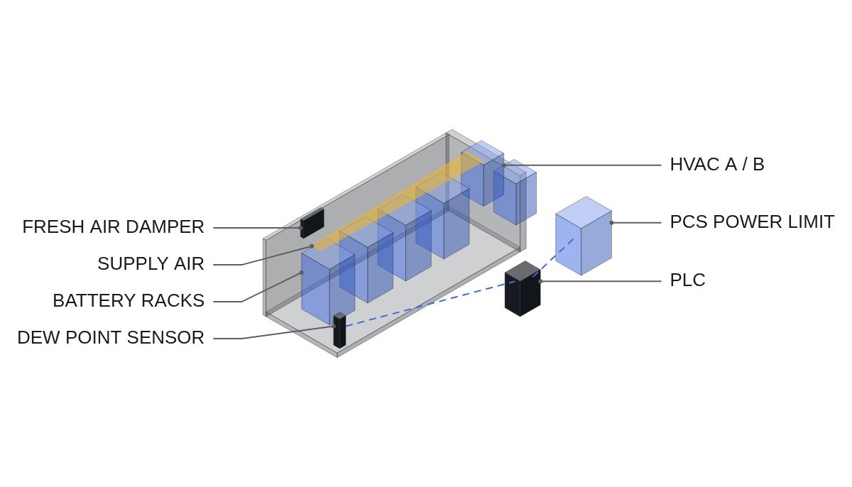
The conclusion first. In normal-mode HVAC control of an ESS container, the control variable most often gotten wrong is not temperature but condensation margin (the gap between surface temperature and room dew point). At summer peak load the problem is cooling capacity, but in low-load, humid seasons over-cooling and fresh-air intake create condensation, and condensation leads to insulation degradation and contact corrosion. Control inputs should not rest on return-air temperature alone; the controller needs BMS maximum cell temperature, rack inlet temperature and room dew point together, and an HVAC fault must link to a PCS power limit. Fire and off-gas response belong to a separate system, and the normal-mode controller is built to give up control when it receives that signal.
Safety interlock conditions first
The normal-mode environmental controller is not a safety system. So first fix what the normal-mode controller does not do.
- □ EMO is a hardwired safety circuit that opens the PCS and the battery DC disconnect. The environmental PLC reads EMO status as a monitoring input only.
- □ On gas (off-gas), smoke or fire detection, exhaust fans, dampers and HVAC are governed hardwired by the fire and explosion-control panel. On that signal the environmental PLC releases its own output commands and does not compete with the fire-side commands.
- □ Confirm on the wiring diagram that the fire-side override is built with contacts in the HVAC and fan start circuits so that it takes precedence over PLC outputs. A priority scheme created by PLC logic alone is not acceptable.
- □ Loss of HVAC power is an input to the decision on whether battery operation continues. Provide a power-limit path so the PCS does not keep delivering rated output without cooling.
With these four lines in place, the rest is control for quality and service life. This article covers only that normal-mode scope.
Choosing control inputs
Temperature inside a container is not uniform. Racks near and far from the supply diffuser, and the top and bottom of each rack, see different inlet temperatures, and return-air temperature is a mix of all of them. Controlling on return temperature alone gets the average right and misses the hottest rack.
| Input | Strength | Limitation | Use |
|---|---|---|---|
| Return air temp | Built into HVAC, fast | Mixed value, hides spread | HVAC internal loop |
| Rack inlet temp | Actual per-rack condition | More sensors | Supply setpoint trim |
| BMS max cell temp | Battery-referenced | Via comms, thermal lag | PCS power limit |
| Room dew point | Condensation margin | Sensor drift | Cooling floor, fresh-air decision |
The table’s conclusion is “split the roles rather than control on one input.” The HVAC runs its own loop on return temperature, the PLC trims the supply setpoint from rack inlet temperature, BMS maximum cell temperature is used only for the PCS power limit, and dew point is used only as the condition for the cooling floor and fresh-air damper. When roles overlap, the two loops fight each other.
Normal-mode control sequence
Time chart premise: two HVAC units (A, B) in N+1, one fresh-air damper, one anti-condensation heater, and a PCS power limit passed as an analog or MODBUS_TCP command.
- Base operation: HVAC A lead, B standby. When accumulated run time exceeds a setpoint, lead and standby swap.
- When the highest rack inlet temperature approaches its upper limit, start B as well. If the rise continues with both running, move to the PCS power-limit stage.
- Clamp the cooling setpoint floor so it never goes below room dew point plus a margin. This is the key condition that prevents over-cooling at low load.
- Open the fresh-air damper only when outdoor dew point is lower than room dew point. Without an outdoor measurement, do not take fresh air in normal mode.
- When condensation margin falls below its threshold, switch on the anti-condensation heater and lower the cooling stage.
- On failure or power loss of both HVAC units, drop the PCS power limit to the minimum stage at once and decide on shutdown from the cell temperature trend.
(* I/O MAP
   %I3.0  DI_EMO_LOOP_OK         : EMO hardwired loop healthy (monitor only)
   %I3.1  DI_FIRE_PANEL_OVERRIDE : fire / off-gas panel has taken HVAC and fans
   %I3.2  DI_HVAC_A_FAULT        : HVAC A fault contact
   %I3.3  DI_HVAC_B_FAULT        : HVAC B fault contact
   %I3.4  DI_DOOR_OPEN           : container door open
   %IW400 AI_RACK_INLET_TMAX     : highest rack inlet temperature, 0.1 degC/digit
   %IW402 AI_ROOM_DEWPT          : room dew point, 0.1 degC/digit
   %IW404 AI_OUT_DEWPT           : outdoor dew point, 0.1 degC/digit
   %IW406 AI_BMS_CELL_TMAX       : BMS highest cell temperature via MODBUS_TCP
   %IW408 AI_RACK_INLET_TMIN     : lowest rack inlet temperature (coldest surface proxy)
   %Q3.0  DO_HVAC_A_RUN          : HVAC A run command
   %Q3.1  DO_HVAC_B_RUN          : HVAC B run command
   %Q3.2  DO_FRESH_AIR_DAMPER    : fresh air damper open
   %Q3.3  DO_ANTI_COND_HEATER    : anti-condensation heater
   %QW400 AO_SUPPLY_T_SP         : HVAC supply air setpoint, 0.1 degC/digit
   %QW402 AO_PCS_P_LIMIT_PCT     : PCS active power limit, 0.1 %/digit
*)
VAR
  NORMAL_CTRL  : BOOL;
  COOL_FLOOR   : INT;   (* lowest allowed supply setpoint = dew point + margin *)
  COND_MARGIN  : INT;
  HVAC_ALL_LOST: BOOL;
END_VAR

(* normal control only when EMO loop healthy and fire panel has not taken over *)
NORMAL_CTRL := DI_EMO_LOOP_OK AND NOT DI_FIRE_PANEL_OVERRIDE;

(* condensation guard: supply setpoint never below room dew point plus margin *)
COOL_FLOOR  := AI_ROOM_DEWPT + DEWPT_MARGIN_SP;
AO_SUPPLY_T_SP := MAX(SUPPLY_T_BASE_SP, COOL_FLOOR);
COND_MARGIN := AI_RACK_INLET_TMIN - AI_ROOM_DEWPT;   (* coldest point decides condensation *)
DO_ANTI_COND_HEATER := NORMAL_CTRL AND (COND_MARGIN < COND_MARGIN_MIN_SP);

(* lead / lag: B starts on high inlet temperature or A fault *)
DO_HVAC_A_RUN := NORMAL_CTRL AND NOT DI_HVAC_A_FAULT;
DO_HVAC_B_RUN := NORMAL_CTRL AND NOT DI_HVAC_B_FAULT
                 AND (DI_HVAC_A_FAULT OR (AI_RACK_INLET_TMAX > INLET_T_STAGE2_SP));

(* fresh air only when outdoor air is drier and door closed *)
DO_FRESH_AIR_DAMPER := NORMAL_CTRL AND NOT DI_DOOR_OPEN
                       AND (AI_OUT_DEWPT < AI_ROOM_DEWPT - DAMPER_DP_MARGIN_SP);

(* PCS derating: loss of both HVAC units or high cell temperature *)
HVAC_ALL_LOST := DI_HVAC_A_FAULT AND DI_HVAC_B_FAULT;
IF HVAC_ALL_LOST OR (AI_BMS_CELL_TMAX > CELL_T_DERATE_SP) THEN
  AO_PCS_P_LIMIT_PCT := P_LIMIT_MIN_PCT;       (* set by thermal study *)
ELSE
  AO_PCS_P_LIMIT_PCT := 1000;                  (* 100.0 % *)
END_IF;
The setpoints in the code (DEWPT_MARGIN_SP, INLET_T_STAGE2_SP, CELL_T_DERATE_SP and so on) come from the cell manufacturer’s operating temperature range and the installation’s thermal study, so they are kept as variables here. Where BMS maximum cell temperature arrives over communications, decide separately how that input is treated when the link drops (for example, assume the worst-case value).
Field verification checklist
- □ Are the fire and explosion-control panel override contacts wired into the HVAC and exhaust fan start circuits so that they take precedence over PLC outputs?
- □ Are rack inlet temperature sensors spread across the rack nearest the supply diffuser, the farthest rack, and top and bottom positions?
- □ Has the dew-point-based clamp on the cooling setpoint floor been confirmed with low-load winter operating data?
- □ Is there no interval in the lead/standby swap where both units are stopped (swap order: confirm start, then stop)?
- □ In a simulated failure of both HVAC units, was the PCS response recorded to confirm that the power limit is actually applied?
- □ Does the fresh-air damper close while the door is open, and is there an alarm for a door left open too long?
- □ Is the effect of auxiliary supply voltage dip at HVAC compressor start on the control supply managed as an item that requires waveform analysis and field measurement?
Boundary conditions
There are conditions under which this design is wrong. First, in liquid-cooled containers, cell temperature control happens in the coolant loop, so air conditioning shrinks to electrical-equipment heat and condensation management, and the priority of control inputs changes. Second, in climates that are dry all year, condensation-margin control gains little and temperature-centered control is enough. Third, in a small container with only one or two racks, distributed rack inlet measurement gains little.
The single decision rule: if the cooling setpoint floor is not tied to room dew point, that container’s normal-mode control was designed for summer only and must be corrected before the low-load season.