Short answer first. Under IEC 60204-1, an emergency stop may only be built as stop category 0 or 1. Category 2 cannot be used for emergency stop. The choice between 0 and 1 should not rest on the intuition that “cutting power immediately is safer”. It should rest on measured stopping distance and stopping time. On high-inertia axes, vertical axes and high-speed rotating parts, category 0 removes power at once and the load coasts, so it often stops later. Category 1, which decelerates the load with the drive before removing power, stops sooner. But the moment you choose category 1, the centre of the design becomes a hardwired delayed disconnect that guarantees power is removed after a fixed time even if the drive fails to decelerate.
Confirm the safety interlocks first
Whichever stop category you choose, the emergency stop circuit must satisfy the following first. All of these are implemented in hardware and are never replaced or bypassed by a PLC program.
- □ Use emergency stop buttons with mechanical latching and direct opening action contacts (IEC 60947-5-5, ISO 13850).
- □ Wire the emergency stop input in two channels directly to the safety inputs of a safety relay or safety PLC, in a configuration that detects cross-channel shorts and earth faults.
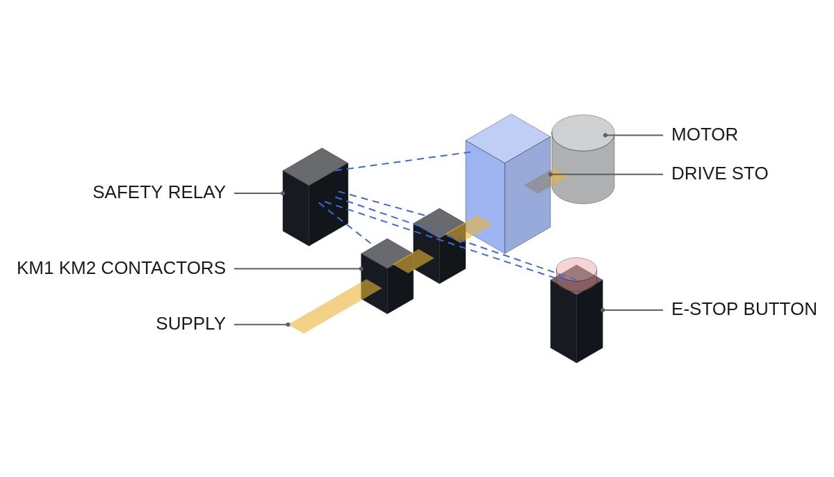
- □ Final disconnection is by two main contactors in series (KM1, KM2) or by two-channel drive STO. Return the contactor mirror contacts to the safety relay as feedback (EDM) to detect welding.
- □ Releasing the emergency stop button or pressing reset alone must never restart the machine. Restart requires a separate start action.
- □ Show on the single-line diagram how the switchgear EMO relates to the machine emergency stop (which one disconnects which scope).
- □ Determine the required performance level (PLr) by risk assessment (ISO 13849-1), and verify that the chosen components and architecture meet it.
Stop categories 0, 1 and 2
| Category | Action | For E-stop | Drive function |
|---|---|---|---|
| Category 0 | Immediate removal of power, uncontrolled stop | Allowed | STO |
| Category 1 | Controlled stop with power available, then power removed | Allowed | SS1 |
| Category 2 | Controlled stop, power left available | Not allowed | SS2, SOS |
The point to read from this table is that category 1 is “category 0 plus deceleration”. Both end in the same state, power removed (STO). The difference is whether the drive gets time to decelerate before power is cut. So the safety of category 1 depends not on whether deceleration succeeds, but on whether it falls back to category 0 within a fixed time when deceleration fails. Drive safety function names (STO, SS1, SS2, SOS) follow the definitions in IEC 61800-5-2.
Selection: decide by stopping distance
In category 0 the motor loses torque and stops only through load inertia and friction. Large rolls, flywheels and high-speed spindles with low friction can keep turning for several seconds or more. In category 1 the drive brakes actively along a set deceleration ramp, so stopping time is shorter. The decision sequence is as follows.
- Measure the category 0 (immediate STO) stopping time for each hazard under worst-case conditions (maximum speed, maximum load).
- Under the same conditions, measure the stopping time with the drive’s emergency deceleration ramp.
- Put both values into the stopping-time term of the safety distance calculation for guards and protective devices (ISO 13855) and compare.
- If category 1 is chosen, set the hardwired delayed disconnect time T_OFF from the measured deceleration time plus a margin.
- For vertical axes, interlock mechanical brake control with STO regardless of category, and set a test interval for the brake’s holding capability.
One judgement is easy to miss here. The longer you set the category 1 delay T_OFF, the longer the stopping time becomes when the drive has failed. Set T_OFF first as the upper limit, the “maximum time still acceptable if the drive has failed”, not as “enough time to decelerate”, and then fit the deceleration ramp inside it. If both conditions cannot hold at once, category 1 is not viable.
Hardwired configuration based on a timing chart
State the premises as a timing chart. At t0 the emergency stop button is pressed. The safety relay’s instantaneous output sends an emergency deceleration request to the drive, and its delayed output opens STO and KM1/KM2 after T_OFF. If the drive stops at t0 + T_DEC (measured deceleration time), it is already at standstill when T_OFF arrives. If the drive fails to decelerate, torque is still removed at T_OFF without exception.
- t0: ES1 pressed → safety relay instantaneous contact opens → drive emergency deceleration input (hardwired)
- t0 to t0 + T_DEC: drive brakes along the emergency deceleration ramp
- t0 + T_OFF: safety relay off-delay contact opens → two-channel STO and KM1/KM2 disconnect
- T_OFF > T_DEC (measured) + margin, and T_OFF ≤ maximum time allowed by the risk assessment
The PLC is not in this path. Its role is status monitoring, resetting the normal sequence after an emergency stop, and managing restart conditions.
(* Emergency stop status monitoring and restart conditions - IEC 61131-3 ST, standard PLC *)
(* E-stop disconnect path: ES1 -> safety relay (instant/off-delay) -> STO, KM1, KM2 (all hardwired) *)
(* This logic is monitoring only; it never energises or bypasses the safety path *)
VAR
  DI_ESTOP_AUX_NC        AT %I2.0 : BOOL;  (* ES1 auxiliary contact, TRUE when healthy *)
  DI_SAFETY_RLY_OUT_OK   AT %I2.1 : BOOL;  (* Safety relay output state auxiliary contact *)
  DI_KM1_MIRROR_NC       AT %I2.2 : BOOL;  (* KM1 mirror contact, TRUE when open *)
  DI_KM2_MIRROR_NC       AT %I2.3 : BOOL;  (* KM2 mirror contact, TRUE when open *)
  DI_DRV_STO_ACTIVE      AT %I2.4 : BOOL;  (* Drive STO active status output *)
  DI_START_PB            AT %I2.5 : BOOL;  (* Start push button *)
  DO_SEQ_RUN_ENABLE      AT %Q2.0 : BOOL;  (* Normal sequence run enable *)
  DO_ESTOP_LAMP          AT %Q2.1 : BOOL;  (* Emergency stop indicator *)
  DO_DISCREPANCY_ALARM   AT %Q2.2 : BOOL;  (* State discrepancy alarm *)
  T_DISC                           : TON;
  START_EDGE                       : R_TRIG;
  SEQ_LATCH                        : BOOL;
END_VAR

(* Drop the normal sequence during E-stop; restart only on a start button rising edge *)
START_EDGE(CLK := DI_START_PB);
IF NOT DI_ESTOP_AUX_NC OR NOT DI_SAFETY_RLY_OUT_OK THEN
  SEQ_LATCH := FALSE;                      (* Reset sequence steps *)
ELSIF START_EDGE.Q AND NOT DI_DRV_STO_ACTIVE THEN
  SEQ_LATCH := TRUE;                       (* Separate start action required after safety path restored *)
END_IF;
DO_SEQ_RUN_ENABLE := SEQ_LATCH;
DO_ESTOP_LAMP := NOT DI_ESTOP_AUX_NC;

(* Discrepancy: safety relay OFF but KM mirror still shows closed -> suspected welding *)
T_DISC(IN := NOT DI_SAFETY_RLY_OUT_OK AND NOT (DI_KM1_MIRROR_NC AND DI_KM2_MIRROR_NC),
       PT := T#500MS);
DO_DISCREPANCY_ALARM := T_DISC.Q;          (* Blocking re-energisation is done by the safety relay EDM *)
The discrepancy alarm is for informing the operator. What prevents re-energisation through a welded contactor is the safety relay’s EDM circuit. A silent PLC alarm does not mean the safety path is healthy.
Commissioning verification checklist
- □ Measure category 0 and category 1 stopping times at maximum speed and maximum load, at least three times each, and record them.
- □ Disconnect the drive’s emergency deceleration input, press the emergency stop, and confirm torque is removed at T_OFF (simulated deceleration failure).
- □ Simulate a fault on the mirror contact of KM1 or KM2 and confirm the safety relay refuses to reset.
- □ Simulate a wire break on one of the two input channels and confirm the discrepancy is detected.
- □ After releasing the emergency stop, confirm that no axis moves without the start button.
- □ Record measured stopping times and the T_OFF setting in the machine documentation, and remeasure whenever a drive is replaced or parameters change.
Boundary conditions
The case for category 1 rests on the premise that the drive can handle regenerative energy. A drive with no braking resistor, or one that is undersized, trips on DC link overvoltage during emergency deceleration and turns itself into category 0. The measured T_DEC then varies from stop to stop, and the basis for category 1 collapses. And on small, low-inertia machines where the stopping-time difference makes no meaningful difference to the safety distance, the simpler category 0 is better. The single decision rule: choose category 1 only when, measured under worst-case conditions, its stopping time is shorter than category 0, that deceleration is repeatable every time, and T_OFF with a failed drive still falls within the allowed time.