Short answer first. Whether to use a safety relay or a safety PLC is not decided by the required performance level (PL) or SIL. Many certified safety relays and safety PLCs, depending on the product, support up to PL e under ISO 13849-1 and SIL 3 under IEC 62061. What actually separates them is the number of safety functions, the conditional combinations between them, and how often they change. If there are few safety functions, they are independent of one another, and they will hardly change over the machine’s life, a safety relay wins because the verification burden is small. If the stop scope changes by zone, if conditional combinations such as muting or mode selection are involved, or if the line is reconfigured often, a safety PLC wins.
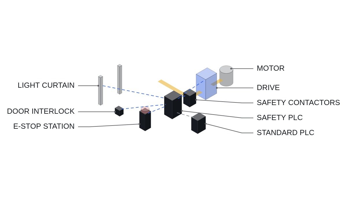
Confirm the safety interlocks first
Some conditions do not change whichever logic solver you choose. Fix these before the selection discussion.
- □ The standard PLC stays out of the safety path. It only reads the safety logic solver’s status and passes on reset requests. It never energises safety outputs directly.
- □ Emergency stop and EMO are hardwired safety circuits. Even with a safety PLC, wire the emergency stop in two channels directly to safety input terminals, never as a network signal alone. The switchgear EMO drives breaker trip circuits directly.
- □ Final switching elements (contactors, drive STO) have two-channel architecture and feedback (EDM), and the logic solver refuses to reset when it detects welding.
- □ Set the PLr or SIL for each safety function by risk assessment first. Choosing the logic solver comes after that.
- □ Leave no software forces, bypass bits or simulation modes in the safety path. If a maintenance bypass is required, attach hardware conditions such as a key switch and speed limitation, and include it in the risk assessment.
What PL and SIL actually rate
ISO 13849-1 PL (a to e) and IEC 62061 SIL (1 to 3) rate an entire safety function, meaning the chain of input device → logic solver → output device. A logic solver with a high rating does not give the whole function that rating. The architecture (category), diagnostic coverage and failure probability of the emergency stop button, door switch and contactors have to be calculated together.
So the reasoning “we need PL e, so we need a safety PLC” is in the wrong order. If only one function needs PL e, a PL e certified safety relay with an appropriate input and output architecture may be enough. Conversely, even at PL c, ten functions that interact with each other make safety relay wiring hard to verify at all.
Comparison by logic solver type
| Item | Single safety relay | Modular safety controller | Safety PLC |
|---|---|---|---|
| Suitable functions | 1 to 2, independent | Several, simple combinations | Many, complex combinations |
| Conditional logic | By wiring, hard to extend | Limited logic in the configuration tool | Freely built with certified function blocks |
| Zone stops | Cascaded relay wiring | Possible within limits | Built in the program |
| Diagnostics | LED level | Per-channel status | Detailed, with upstream communication |
| Cost of change | Rewire, then re-verify | Change settings, then re-verify | Program change management and re-verification |
| What is verified | Wiring and architecture | Wiring and settings | Wiring and safety program (incl. software verification) |
The last two rows decide the cost. With a safety PLC the burden per function falls as functions are added, but software verification of the safety program and a change management procedure come as a fixed cost. A safety relay has almost no fixed cost, but the wiring verification burden grows quickly as functions are added. Where the two curves cross is the selection point, and that point is more sensitive to the number of conditional combinations between functions than to the number of functions.
Selection sequence: an execution checklist
- Confirm the list of safety functions and the PLr of each through risk assessment.
- Mark for each function whether its behaviour changes depending on the state of another function. Zone stops, mode selection and muting belong here.
- Classify functions without combinations as safety relay candidates, and functions with combinations as safety controller or safety PLC candidates.
- Check how often layout or process changes are expected over the machine’s life. Frequent changes raise the score for the safety PLC.
- Check whether site maintenance staff can operate a safety program change management procedure. If they cannot, a simpler configuration is safer.
- After selection, redo the PL calculation per function (component MTTFd, DC, CCF) and confirm it meets or exceeds PLr.
Standard PLC side: status display and reset requests only
The safety logic itself is written inside the safety PLC with certified safety function blocks and is not covered here. Below is the part where the standard PLC reads the safety PLC status over PROFISAFE or mapped I/O, displays the cause of a zone stop, and passes on reset requests.
(* Standard PLC: safety status display and reset request - IEC 61131-3 ST *)
(* Safety trip decisions and reset acceptance are made by the safety PLC. Standard PLC only forwards requests *)
VAR
  DI_SF_ZONE1_OK        AT %I4.0 : BOOL;  (* Zone 1 safety functions healthy, safety PLC status output *)
  DI_SF_ZONE2_OK        AT %I4.1 : BOOL;  (* Zone 2 safety functions healthy *)
  DI_SF_ESTOP_OK        AT %I4.2 : BOOL;  (* E-stop chain healthy - monitoring only *)
  DI_SF_LC_MUTING       AT %I4.3 : BOOL;  (* Light curtain muting active *)
  DI_SF_EDM_FAULT       AT %I4.4 : BOOL;  (* Output contactor feedback fault *)
  DI_RESET_PB           AT %I4.5 : BOOL;  (* Reset button, located with view of hazard zone *)
  DO_RESET_REQ_TO_SF    AT %Q4.0 : BOOL;  (* Reset request pulse to safety PLC *)
  DO_ZONE1_RUN_ENABLE   AT %Q4.1 : BOOL;  (* Zone 1 normal sequence enable *)
  DO_ZONE2_RUN_ENABLE   AT %Q4.2 : BOOL;  (* Zone 2 normal sequence enable *)
  HMI_TRIP_CAUSE                 : INT;   (* 0 normal, 1 E-stop, 2 zone 1, 3 zone 2, 9 EDM *)
  TP_RST                         : TP;
  RST_EDGE                       : R_TRIG;
END_VAR

(* Stop cause display - priority: EDM fault > E-stop > zones *)
IF DI_SF_EDM_FAULT THEN HMI_TRIP_CAUSE := 9;
ELSIF NOT DI_SF_ESTOP_OK THEN HMI_TRIP_CAUSE := 1;
ELSIF NOT DI_SF_ZONE1_OK THEN HMI_TRIP_CAUSE := 2;
ELSIF NOT DI_SF_ZONE2_OK THEN HMI_TRIP_CAUSE := 3;
ELSE HMI_TRIP_CAUSE := 0;
END_IF;

(* Reset request: forward only a 500 ms pulse on the button rising edge. Acceptance is the safety PLC's call *)
RST_EDGE(CLK := DI_RESET_PB);
TP_RST(IN := RST_EDGE.Q, PT := T#500MS);
DO_RESET_REQ_TO_SF := TP_RST.Q AND NOT DI_SF_EDM_FAULT;

(* Zone sequence enables - separate from safety disconnection, used to hold process steps *)
DO_ZONE1_RUN_ENABLE := DI_SF_ESTOP_OK AND DI_SF_ZONE1_OK;
DO_ZONE2_RUN_ENABLE := DI_SF_ESTOP_OK AND DI_SF_ZONE2_OK;
In this structure, a failure of the standard PLC does not affect safety disconnection. All that is lost is the display and the process sequence. If communication errors between the standard PLC and the safety PLC occur intermittently, do not conclude it is noise; it requires waveform analysis and field measurement. During commissioning, confirm that a lost link drops the zone enables.
Boundary conditions
There are cases where this reasoning flips. First, if the party supplying the machine and the party operating it are different, and the operator has no capability to manage safety program changes, a modular safety controller with a narrow scope of change is actually safer even with many functions. Easy program changes are both an advantage and a risk of unauthorised modification. Second, if the robots or servo drives already carry built-in safety functions, and the external logic solver is left with just the emergency stop and a few doors, the safety PLC’s advantage nearly disappears. The single decision rule: choose a safety PLC if at least one safety function behaves differently depending on the state of another, and there is a procedure and staff to manage its changes; if either is missing, choose a safety relay or a modular controller.