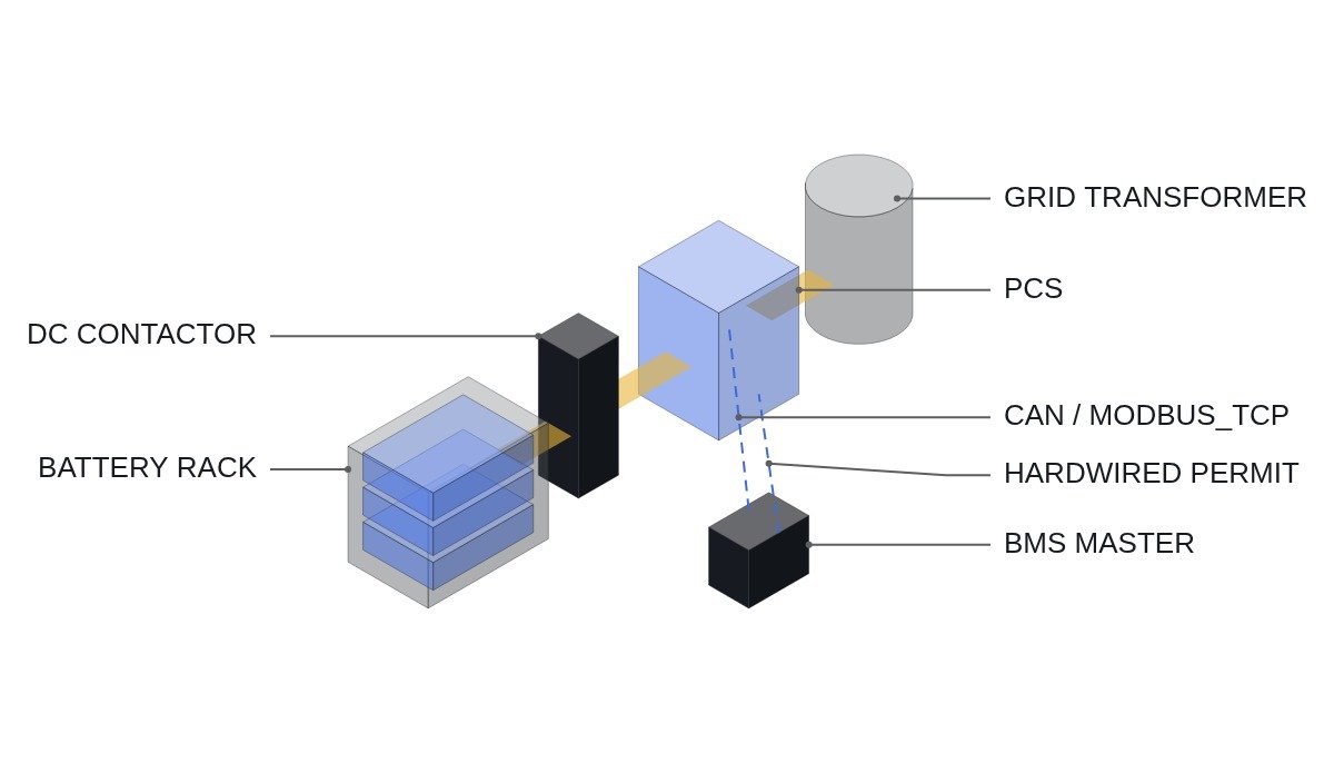
The conclusion first. The fail-safe timeout for loss of BMS-PCS communication (CAN, MODBUS_TCP) should be set not by communication convention but by the time remaining before the cells reach a limit at the present operating point. Running at low current in mid-SOC, holding the last values for a few seconds is harmless; in the high-current end-of-charge region, the same few seconds can be enough to cross a limit. And a live communication link is not the same thing as fresh data, so alive-counter supervision is mandatory alongside link supervision. The last line of defense is a hardwired permit contact that does not depend on communication at all.
Safety interlock conditions first
Communication is a means of optimizing operation, not a means of safety. A path that protects the cells with communication completely gone must exist first; only then is behavior on communication loss designed.
- □ EMO is a hardwired safety circuit that opens the PCS AC and DC sides and the rack DC contactors. The PLC and PCS controller read EMO status as a monitoring input only.
- □ The BMS must be able to open the rack DC contactor on its own decision for cell overvoltage, undervoltage and overtemperature. This path works even when communication with the PCS is lost.
- □ The BMS run permit is also passed to the PCS as a voltage-free contact (DI_BMS_PERMIT_HW), separately from the communication data. It is wired normally closed, so a broken wire reads as permit lost.
- □ The DC contactor is not used to break load current. A sequence drives PCS current to zero before opening, and opening under current is allowed only in an emergency (the contactor’s breaking rating must be confirmed).
With these four conditions in place, the purpose of the communication fail-safe is not “safety” but “ramping down smoothly before the safety path has to act, while avoiding unnecessary trips.”
Communication failure types and detection
Communication loss is not a single failure. A pulled cable is easy to catch with a timeout, but a BMS application that has frozen while its communication stack stays alive and keeps sending the same values is not caught by a timeout.
| Failure type | Symptom | Detection |
|---|---|---|
| Physical break | No frames received | Receive timeout |
| BMS app frozen | Link up, values fixed | Alive counter stops |
| Gateway delay | Values arrive but old | Timestamp age |
| Bad value | Out-of-range value | CRC, range, rate checks |
| Bus overload, noise | Intermittent loss | Loss-rate count (requires waveform analysis and field measurement) |
The second row is the most dangerous. On MODBUS_TCP, the TCP session can be alive and register reads can succeed while the values are minutes old. Equipment whose register map carries no alive counter or BMS-side timestamp cannot, in principle, detect this failure.
Setting the timeout from the operating point
SOC changes at a rate set by current (C-rate). 1C is 100% per hour, so 36 s per 1% SOC. At 0.5C it is 72 s per 1%, at 2C 18 s. On top of that, near end of charge there is a region where voltage rises steeply for a small SOC increase, so the real margin should be taken as shorter than the SOC calculation suggests.
Assumptions: SOC margin before the voltage limit is 2%, operating current 1C, so the time margin is about 72 s. A 5 s last-value hold is then about 7% of the margin, small enough. With a 0.5% margin at 2C, the time margin is about 9 s, and a 5 s hold uses more than half of it. The same timeout value can be safe or dangerous depending on the operating point. So the hold time is set to the smaller of a fixed value and a fixed fraction of the time margin.
Staged fail-safe sequence
- T1 (hold): after a communication fault is detected, keep the last current limit, but never longer than the hold time allowed at the operating point.
- T2 (ramp down): ramp the current command to zero at a set slope, converging to zero regardless of direction (charge or discharge).
- T3 (stop): after confirming zero current, remove the PCS run permit and request the rack DC contactor to open.
- If the hardwired permit contact drops, skip T1 and T2 and go straight to T3.
- Restart requires, ANDed together: communication restored, continuous alive-counter increments confirmed, no BMS alarms, operator reset. No automatic restart.
(* I/O MAP
   %I4.0  DI_EMO_LOOP_OK        : EMO hardwired loop healthy (monitor only)
   %I4.1  DI_BMS_PERMIT_HW      : BMS run permit dry contact, NC wiring
   %I4.2  DI_RESET_PB           : operator reset
   %IW500 BMS_ALIVE_CNT         : BMS alive counter via CAN / MODBUS_TCP
   %IW502 AI_BMS_CHG_I_LIM      : BMS charge current limit, 0.1 A/digit
   %IW504 AI_BMS_DSG_I_LIM      : BMS discharge current limit, 0.1 A/digit
   %IW506 AI_BMS_SOC_MARGIN     : SOC margin to nearest voltage limit, 0.1 %/digit
   %IW508 AI_PCS_DC_I           : PCS DC current, 0.1 A/digit, +charge / -discharge
   %QW500 AO_PCS_I_LIM          : current limit to PCS, 0.1 A/digit
   %Q4.0  DO_PCS_RUN_PERMIT     : PCS run permit
   %Q4.1  DO_DC_CONT_OPEN_REQ   : rack DC contactor open request to BMS
*)
VAR
  LAST_CNT      : INT;
  T_STALE       : TON;    (* alive counter not changing *)
  COMM_FAULT    : BOOL;
  HOLD_LIMIT_MS : DINT;   (* operating-point based hold time *)
  T_HOLD        : TON;
  I_CMD         : REAL;
  STATE         : INT;    (* 0 normal, 1 hold, 2 ramp down, 3 stopped *)
END_VAR

(* stale detection: counter must change within ALIVE_TO; link-up alone is not healthy *)
T_STALE(IN := (BMS_ALIVE_CNT = LAST_CNT), PT := T#500MS);   (* example value *)
LAST_CNT := BMS_ALIVE_CNT;
COMM_FAULT := T_STALE.Q;

(* hold time = min(fixed max, 10 % of time to limit); time to limit = margin / C-rate *)
HOLD_LIMIT_MS := MIN(HOLD_MAX_MS, TIME_TO_LIMIT_MS(AI_BMS_SOC_MARGIN, AI_PCS_DC_I) / 10);

CASE STATE OF
  0: IF COMM_FAULT THEN STATE := 1; END_IF;
     I_CMD := MIN(AI_BMS_CHG_I_LIM, AI_BMS_DSG_I_LIM);
  1: T_HOLD(IN := TRUE, PT := DINT_TO_TIME(HOLD_LIMIT_MS));
     IF NOT COMM_FAULT THEN STATE := 0; T_HOLD(IN := FALSE);
     ELSIF T_HOLD.Q THEN STATE := 2; T_HOLD(IN := FALSE); END_IF;
  2: I_CMD := MAX(0.0, I_CMD - RAMP_A_PER_SCAN);           (* ramp to zero *)
     IF (I_CMD = 0.0) AND (ABS(AI_PCS_DC_I) < I_ZERO_BAND) THEN STATE := 3; END_IF;
  3: I_CMD := 0.0;
     IF NOT COMM_FAULT AND DI_BMS_PERMIT_HW AND DI_RESET_PB THEN STATE := 0; END_IF;
END_CASE;

(* hardwired permit loss skips hold and ramp *)
IF NOT DI_BMS_PERMIT_HW OR NOT DI_EMO_LOOP_OK THEN STATE := 3; I_CMD := 0.0; END_IF;

AO_PCS_I_LIM        := REAL_TO_INT(I_CMD * 10.0);
DO_PCS_RUN_PERMIT   := (STATE < 3) AND DI_BMS_PERMIT_HW AND DI_EMO_LOOP_OK;
DO_DC_CONT_OPEN_REQ := (STATE = 3);
The 500 ms alive timeout and the 10% hold ratio are examples. They are set from the BMS transmit period, gateway conversion delay and PCS current response, and because message loss rate depends on bus load and wiring condition, they are finalized after waveform analysis and field measurement on site. TIME_TO_LIMIT_MS is assumed to be a function that returns the SOC margin divided by the present C-rate.
Boundary conditions
There are conditions under which this design is wrong. First, if the BMS does not provide SOC margin or distance to a voltage limit in its registers, an operating-point hold time cannot be calculated, and the design has to fall back to a short fixed value based on the worst operating point. Second, during grid-forming operation or grid-support commands, ramping current to zero can itself disturb the grid, so it has to be reviewed together with grid-side requirements. Third, if the premise that the BMS’s own protection acts independently on communication loss has not been confirmed by test, this fail-safe sequence must be promoted to primary protection, and the design basis changes with it.
The single decision rule: if the last-value hold time on communication loss is a fixed value independent of the operating point, first confirm by calculation that it is well below the time to limit at maximum current near end of charge.