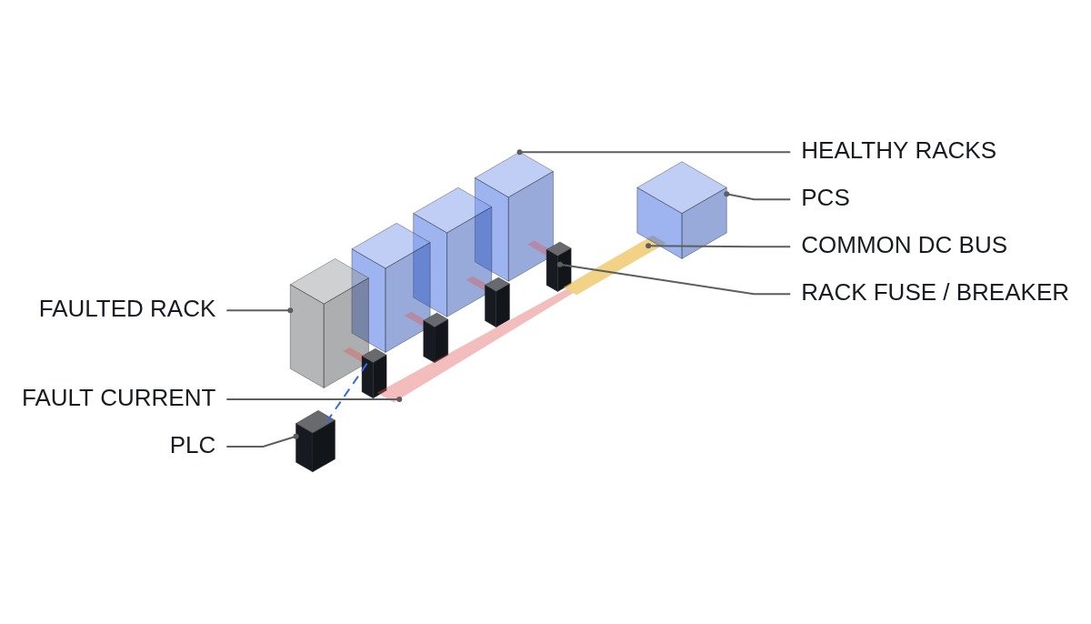
The conclusion first. In coordinating DC-side breakers and fuses in an ESS, the first thing to look at is not rated current but which direction fault current comes from and over what range. In a parallel-rack configuration, a fault in one rack is fed in reverse by every other rack through the DC bus, so the rack-level protective device has to interrupt “the sum of the other racks,” not its own rack’s current. Battery fault current also varies widely with temperature, SOC and ageing, so interrupting capacity has to be checked at the maximum condition and operating time at the minimum condition, separately. Finally, a DC contactor is not a device for breaking fault current, so the control logic needs a contactor open-inhibit condition.
Safety interlock conditions first
- □ EMO is a hardwired safety circuit that directly operates the DC breaker shunt trip coil (or undervoltage release) and the PCS stop circuit. The PLC reads EMO status as a monitoring input only.
- □ Confirm that the DC breakers and fuses are guaranteed to interrupt in both directions (non-polarized). A polarity-dependent DC breaker may not have guaranteed interrupting performance for reverse fault current, and in a battery circuit the current direction changes with charge, discharge and backfeed.
- □ If the BMS or PLC detects overcurrent while the current is above the contactor’s breaking rating, it must not command the contactor open; interruption is left to the fuse and breaker. A contactor that welds while trying to break fault current leaves the system without its means of isolation afterwards.
- □ Fuse-blown microswitches, breaker trip auxiliary contacts and contactor auxiliary contacts all come into the PLC so that state mismatches (for example, fuse healthy but zero current) can be detected.
- □ Isolation for maintenance follows breaker open + disconnect + verify absence of voltage, and the work procedure is written on the premise that the rack side stays energized even after interruption.
Range and direction of fault current
Battery short-circuit current is approximately I ≈ V_oc / (R_batt + R_cable). The problem is that V_oc and R_batt are not fixed. Internal resistance rises at low temperature, open-circuit voltage is lower at low SOC, and internal resistance rises again with ageing.
Assumptions: rack open-circuit voltage 800 V, total rack internal resistance 50 mΩ (new, room temperature, full charge), cable 5 mΩ, giving I ≈ 800 / 0.055 ≈ 14.5 kA. If the same rack reaches 100 mΩ internal resistance from cold and ageing and 700 V open-circuit voltage at low SOC, I ≈ 700 / 0.105 ≈ 6.7 kA. Fault current from the same rack can differ by more than a factor of two; interrupting capacity is checked at the 14.5 kA end and fuse melting time at the 6.7 kA end.
Direction matters as well. With four racks in parallel and a fault inside rack 1 or in its rack-to-bus cable, racks 2 to 4 drive current toward rack 1 through the bus. An upper-bound approximation ignoring bus impedance gives 3 × 14.5 kA ≈ 43.5 kA. Bus and cable impedance bring the real value down, but rack 1’s protective device has to be able to interrupt this summed reverse current, not the current its own rack produces. If rack 1’s fuse does not clear, the fuses of racks 2 to 4 blow first and the whole system shuts down in a non-selective trip.
Comparison by protective device
| Item | DC fuse | DC breaker | DC contactor |
|---|---|---|---|
| Main role | Fast fault interruption | Overload and fault trip, reclose | Operational switching, isolation |
| Fault interruption | Yes (current limiting) | Within breaking capacity | Within rating only, avoided in principle |
| Polarity | Non-polarized | Check per product | Check per product |
| After operation | Replace | Reclosable | Repeated switching |
| Remote control | No (status only) | Yes, via trip coil | Yes |
The way to read the table is that “the three devices do not substitute for one another.” The fuse limits and clears the maximum fault current, the breaker handles remote tripping and reclosing, and the contactor only switches during normal operation. In a design review it matters more to find the gaps (current ranges no device is responsible for) than the overlaps between operating regions.
Coordination check order
- Tabulate maximum and minimum fault current per rack together with the conditions (temperature, SOC, ageing). The cell manufacturer’s internal resistance data is the basis; where it is missing, keep it as an item to verify.
- Calculate reverse fault current reflecting the number of parallel racks. Record both the calculation that includes bus and cable impedance and the upper-bound approximation.
- Calculate the circuit time constant (L/R) and compare it with the time constant under which the breaker’s and fuse’s DC interrupting performance is specified in the product data.
- Confirm from time-current characteristics that at minimum fault current the rack fuse operates before the upstream breaker, and before cell damage.
- Set the contactor open-inhibit current from the contactor’s breaking rating and put it into the BMS and PLC logic.
- Review IEC 60269-7 (fuses for battery protection), IEC 60947-2 (circuit-breakers), NEC Article 706 (energy storage systems) and the IEC 62933 series together.
PLC supervision and interruption order logic
(* I/O MAP
   %I5.0  DI_EMO_LOOP_OK        : EMO hardwired loop healthy (monitor only)
   %I5.1  DI_RACK1_FUSE_OK      : rack 1 fuse microswitch, NC = fuse healthy
   %I5.2  DI_RACK1_CB_TRIPPED   : rack 1 DC breaker trip auxiliary contact
   %I5.3  DI_RACK1_K_CLOSED     : rack 1 DC contactor auxiliary contact
   %IW600 AI_RACK1_I            : rack 1 current, 1 A/digit, signed
   %IW602 AI_RACK1_V            : rack 1 terminal voltage, 0.1 V/digit
   %IW604 AI_BUS_V              : DC bus voltage, 0.1 V/digit
   %Q5.0  DO_RACK1_K_CLOSE      : rack 1 DC contactor close command
   %Q5.1  DO_RACK1_CB_SHUNT     : rack 1 breaker shunt trip (control path, EMO is separate)
   %Q5.2  DO_PCS_STOP_REQ       : PCS stop request
*)
VAR
  OVERCURRENT   : BOOL;
  K_OPEN_INHIBIT: BOOL;   (* current above contactor breaking rating *)
  PATH_MISMATCH : BOOL;
  T_MISMATCH    : TON;
END_VAR

(* normal precharge / close sequence omitted; this block handles fault response only *)
OVERCURRENT    := ABS(AI_RACK1_I) > RACK_OC_SP;
K_OPEN_INHIBIT := ABS(AI_RACK1_I) > K_BREAK_RATING_SP;   (* from contactor datasheet *)

(* overcurrent: stop PCS first; open contactor only below its breaking rating *)
DO_PCS_STOP_REQ := OVERCURRENT OR NOT DI_RACK1_FUSE_OK OR DI_RACK1_CB_TRIPPED;

IF (OVERCURRENT OR NOT DI_RACK1_FUSE_OK OR DI_RACK1_CB_TRIPPED) AND NOT K_OPEN_INHIBIT THEN
  DO_RACK1_K_CLOSE := FALSE;                 (* safe to open: current within rating *)
ELSIF K_OPEN_INHIBIT THEN
  DO_RACK1_CB_SHUNT := TRUE;                 (* leave interruption to breaker / fuse *)
END_IF;

(* state mismatch: contactor closed, fuse healthy, but rack voltage differs from bus *)
T_MISMATCH(IN := DI_RACK1_K_CLOSED AND DI_RACK1_FUSE_OK
                 AND (ABS(AI_RACK1_V - AI_BUS_V) > V_MISMATCH_SP), PT := T#2S);
PATH_MISMATCH := T_MISMATCH.Q;               (* alarm: check fuse, joints, contactor *)

IF NOT DI_EMO_LOOP_OK THEN DO_RACK1_K_CLOSE := FALSE; END_IF;   (* monitor only; EMO acts by hardware *)
K_BREAK_RATING_SP comes from the DC breaking rating in the contactor datasheet, lowered conservatively if the specified time constant differs from the installation. The voltage mismatch threshold (V_MISMATCH_SP) has to account for current-dependent voltage drop and is used to catch rising joint resistance from connection heating early. Current sensor response speed and noise require waveform analysis and field measurement.
Boundary conditions
There are conditions under which this design is wrong. First, if the racks are not paralleled directly but each connects to the bus through its own DC/DC converter, the converter limits reverse fault current and the reverse interrupting burden on the rack fuse drops sharply. Second, in a single-rack system there is no summed reverse current, and coordination reduces to two levels: the rack fuse and the PCS-side protection. Third, if the cell manufacturer does not provide internal resistance data by temperature and SOC, there is no basis for calculating minimum fault current, and without a measured short-circuit test the basis for fuse selection is incomplete.
The single decision rule: if the rack protective device’s interrupting capacity was selected from “its own rack’s short-circuit current,” recheck it against the summed reverse current for the number of parallel racks, and confirm from product data that interrupting performance in that direction is guaranteed.