Short answer first. When you deal with harmonics from inverter loads, the choice between a passive filter and an active harmonic filter (AHF) is not decided by filter performance. It is decided by the load factor profile and the resonance condition at the point of supply. If the load is nearly constant, light-load hours are short, and resonance with the existing power factor correction capacitors has already been checked, a tuned passive filter is the economical choice. If the load swings constantly, night and weekend light-load periods are long, and the upstream network already shows background voltage distortion, the AHF wins. The right order is not “pick a filter, then make the conditions fit”. Calculate the load profile and the resonance frequency first, then pick the filter.
Confirm the safety interlocks first
Harmonic filters get filed under “power quality equipment” and often slip through safety review. But a passive filter is an energy storage assembly made of capacitors and reactors, and an AHF is a power converter with a DC link capacitor. Both keep residual voltage after they are switched off. Fix the following in hardware before writing any logic.
- □ Filter panel door interlock: the door must not open until the filter breaker (52F) is open and discharge is complete. Use a mechanical key interlock or a discharge indicator lamp. Under IEC 60831-1, LV power capacitors must have a discharge device that brings them to 75 V or less within 3 minutes after disconnection. Test for dead before work regardless.
- □ Reactor overtemperature trip: wire the temperature switch contact of the tuning reactor directly into the 52F trip coil circuit. The PLC only monitors it.
- □ Main breaker coordination: a passive filter must be disconnected together with the main breaker (52M) or when the load bus goes to no-load. A filter capacitor left on without load pushes leading reactive power into the bus and raises the voltage.
- □ EMO (Emergency Off): the switchgear EMO is a hardwired safety circuit that trips 52M and 52F directly. It does not pass through the filter controller or the PLC.
What the two approaches actually do
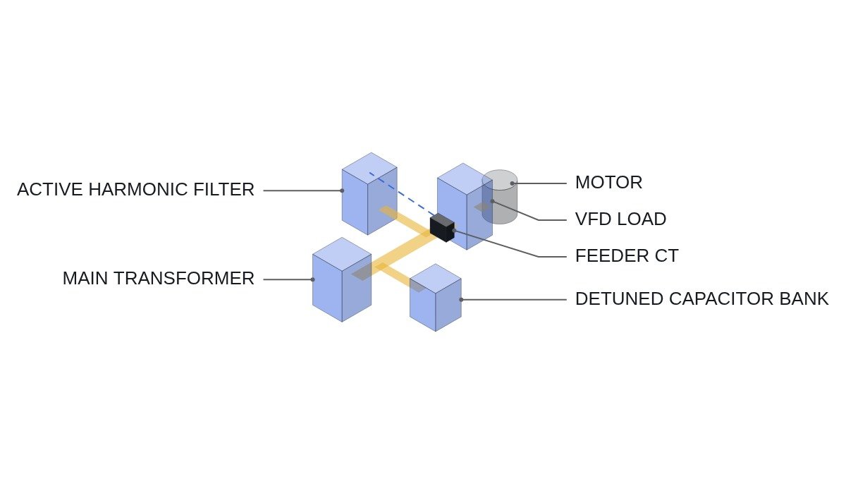
An inverter with a 6-pulse diode rectifier input produces characteristic harmonic currents at the 5th, 7th, 11th and 13th orders (h = 6k ± 1). A tuned passive filter presents a low impedance at a chosen order and draws that harmonic current into itself. It is usually tuned just below the 5th so that the parallel resonance with the network does not land exactly on the 5th.
An AHF measures the load current with CTs and uses an IGBT inverter to inject a current of equal magnitude and opposite phase to the harmonic components. Because it compensates the measured load current, the compensation follows the load. Its rating is stated not in kvar but in compensable harmonic current (A).
There is one difference that is often missed in the field. A passive filter does not absorb only the harmonics of its own load. Its impedance is low at the tuned frequency, so current driven by background voltage harmonics already present upstream also flows into it. If a neighbouring customer or another load on the same transformer is generating harmonics, your filter ends up carrying that current too and trips on reactor overtemperature. An AHF compensates against load-side CTs, so this problem is structurally small.
Comparison: passive vs active filter
| Item | Tuned passive | Active (AHF) |
|---|---|---|
| Principle | LC series resonance absorbs one order | CT measurement, anti-phase injection |
| Load tracking | Fixed (stepwise if switched in stages) | Real time |
| At light load | Excess leading kvar, bus voltage rise | Compensation drops automatically |
| Resonance | Must be checked against existing capacitors and network | Little resonance risk (within control bandwidth) |
| Background distortion | May absorb upstream harmonics and overload | Load-side CT reference, small effect |
| Rating | kvar, tuned order | Compensation current in A |
| Losses, upkeep | Reactor heating, capacitor ageing | Switching loss, fans and DC capacitor ageing |
The two rows that decide the case are “At light load” and “Background distortion”. On price and performance alone the passive filter looks better, but when low-load hours are long or the upstream network is already distorted, it creates new problems: voltage rise and overload trips. The passive filter’s price advantage survives only in plants where neither condition exists.
Decision sequence: calculate resonance first
The parallel resonance order at the point of supply is approximately hr ≈ √(Ssc / Qc), where Ssc is the short-circuit power at the supply point (MVA) and Qc is the connected capacitor rating (Mvar).
Assumption: short-circuit power at the transformer secondary of 20 MVA, with 500 kvar of power factor correction capacitors connected. hr ≈ √(20 / 0.5) = √40 ≈ 6.3. The resonance sits between the 5th and 7th, so adding inverter load here could amplify 5th and 7th voltage distortion with nothing more than the existing capacitors. Before discussing filters at all, the first action is to replace those capacitors with detuned (reactor-equipped) units. How much amplification actually occurs depends on network impedance and load conditions, so this requires waveform analysis and field measurement.
- Record voltage THD, current TDD and the harmonic spectrum at the supply point with a power quality analyser for at least one week, including working days and holidays.
- Build the load factor profile by time of day and find the share of time spent below 30% of rated load.
- Calculate the resonance order from the existing capacitor bank rating and the short-circuit power.
- Check line-side AC reactors or DC chokes on the inverters first. If this low-cost measure reaches the target, no filter is needed.
- Set the target at the point of common coupling (PCC), using IEEE 519 or whichever limit the utility actually applies in the supply contract. Do not confuse equipment-level compliance (IEC 61000-3-12) with the supply-point limit.
- Choose passive, active, or hybrid (passive filter for the steady 5th, AHF for the varying part) based on the results above.
Monitoring logic: the PLC only monitors and grants permits
Filter protection belongs to the filter controller and the hardwired trips. The PLC reads power quality values over MODBUS_TCP, raises alarms, and manages only the permit signal that blocks capacitor bank step switching. The I/O addresses below are examples.
(* Harmonic monitoring and capacitor step permit - IEC 61131-3 ST *)
(* Premise: 52F trip, reactor overtemperature trip and EMO are handled in hardwired circuits. Monitoring only *)
VAR
  DI_MAIN_52M_CLOSED     AT %I0.0  : BOOL;  (* Main breaker closed *)
  DI_FILTER_52F_CLOSED   AT %I0.1  : BOOL;  (* Filter breaker closed *)
  DI_AHF_READY           AT %I0.2  : BOOL;  (* AHF ready *)
  DI_AHF_FAULT           AT %I0.3  : BOOL;  (* AHF fault contact, wired NC *)
  DI_REACTOR_OT_TRIPPED  AT %I0.4  : BOOL;  (* Reactor overtemperature trip occurred - monitoring only *)
  AI_PQM_THDV_PCT        AT %IW100 : INT;   (* Supply-point voltage THD x10, MODBUS_TCP mapped *)
  AI_PQM_TDDI_PCT        AT %IW102 : INT;   (* Supply-point current TDD x10 *)
  AI_LOAD_PCT            AT %IW104 : INT;   (* Load factor, % of rated *)
  DO_AHF_RUN_PERMIT      AT %Q0.0  : BOOL;  (* AHF run permit *)
  DO_CAP_STEP_INHIBIT    AT %Q0.1  : BOOL;  (* Inhibit capacitor step switching *)
  DO_HARMONIC_ALARM      AT %Q0.2  : BOOL;  (* Harmonic alarm lamp *)
  PQM_COMM_OK                      : BOOL;  (* MODBUS_TCP communication healthy flag *)
  T_THDV_HOLD                      : TON;   (* Alarm delay *)
  THDV_LIMIT_X10                   : INT := 50; (* Assumed setpoint, adjust to contract limit *)
END_VAR

(* AHF run permit: main breaker closed AND ready AND no fault *)
DO_AHF_RUN_PERMIT := DI_MAIN_52M_CLOSED AND DI_AHF_READY AND NOT DI_AHF_FAULT;

(* Capacitor step inhibit conditions *)
(* 1) AHF fault removes the resonance damping means, so block further steps *)
(* 2) Below 30% load, prevent excess leading kvar *)
(* 3) Metering link lost means no basis for decision, so fail to inhibit *)
DO_CAP_STEP_INHIBIT := DI_AHF_FAULT
                       OR (AI_LOAD_PCT < 30)
                       OR NOT PQM_COMM_OK
                       OR DI_REACTOR_OT_TRIPPED;

(* Voltage THD alarm: above setpoint for 60 s *)
T_THDV_HOLD(IN := PQM_COMM_OK AND (AI_PQM_THDV_PCT > THDV_LIMIT_X10), PT := T#60S);
DO_HARMONIC_ALARM := T_THDV_HOLD.Q OR DI_REACTOR_OT_TRIPPED;
The key point is that a lost link is not treated as “normal” but as a reason to inhibit. A MODBUS_TCP dropout from the power quality meter could be noise or could be a configuration issue, so the cause is left open: it requires waveform analysis and field measurement.
Commissioning checklist
- □ Confirm the AHF CTs are on the load side and CT polarity (P1/P2) matches the manual. Reversed polarity amplifies harmonics instead of cancelling them.
- □ Measure bus voltage and power factor before and after switching in the passive filter, under light-load conditions.
- □ With the filter in service, measure current per harmonic order and record the margin against the reactor current rating.
- □ Test the filter panel door interlock, discharge indicator lamp and reactor temperature trip by actual operation.
- □ If an expansion is planned, recalculate the resonance order with the post-expansion load.
Boundary conditions
Two conditions make this reasoning wrong. First, if most of the inverters have AFE (Active Front End) inputs or 12-pulse or higher rectifiers, the 5th and 7th components are small to begin with and the filter choice disappears. The problem shifts to high-order components around the switching frequency, which neither passive filters nor typical AHFs target, so they need separate measurement. Second, if the short-circuit power at the supply point is very large relative to the load, voltage distortion is small from the start and a filter brings no benefit beyond meeting the contract limit. The single decision rule: if light-load hours are long or background distortion upstream is measured, choose the AHF; if neither applies and the resonance order sits well away from the tuned order, choose the passive filter.