The conclusion first. Whether an energy-recovery (regenerative) formation and cycling system beats a resistive-dissipation system is not decided by equipment price. It is decided by how much the discharge steps of the recipe are staggered across channels. When discharging and charging channels coexist, energy is reused directly inside a shared DC bus and only the surplus goes back to the grid. When every channel discharges at the same moment under a synchronized recipe, most of the recovered energy is exported to the grid, and from that point the design revolves around reverse-power interlocks and DC bus overvoltage protection.
Safety interlock conditions first
A regenerative cycler treats the cell as a source, not a load. A discharging cell keeps pushing energy even when the grid disappears, so the interlock has to be built around “loss of the recovery path,” not “loss of supply.” All of the conditions below must hold before RUN_PERMIT is issued.
- □ EMO is a hardwired safety circuit that directly opens the AC input breaker and the channel output relays. The PLC reads EMO status as a monitoring input only.
- □ If AC-side grid voltage or frequency leaves its permitted range, regenerating (discharging) channels stop first. Charging channels stop after that.
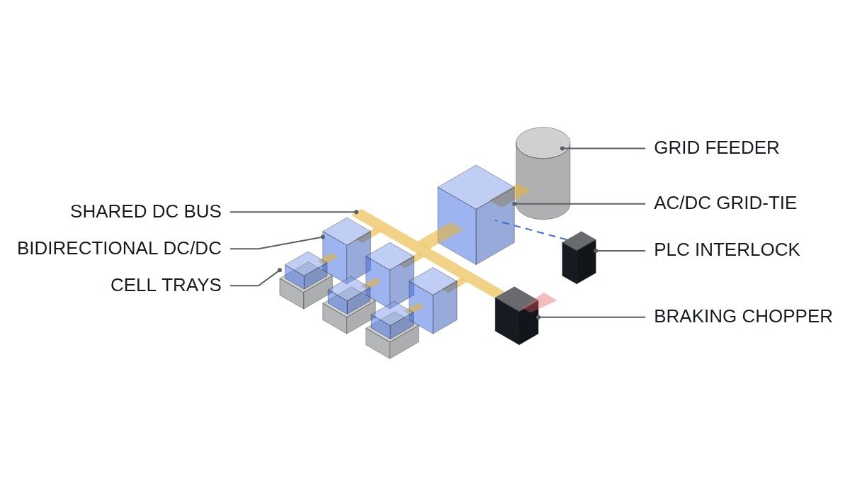
- □ If DC bus voltage exceeds the overvoltage setpoint, the braking chopper acts first through a hardware comparator; the PLC receives that signal and drives the discharge command to zero.
- □ A tray probe contact fault (open voltage-sense lead) is an immediate per-channel stop. Current without sensing is never allowed.
- □ Formation-room temperature and smoke signals are owned by the fire system; the cycler responds to them only by stopping all channels.
Order is the point. If the grid disappears and the charging channels are cut first, the discharging channels lose their sink and the DC bus voltage jumps. The stop order is “regenerating sources first, consumers last.”
Structural difference between dissipative and recovery types
The dissipative type burns cell discharge energy as heat in per-channel load resistors or linear devices. It is simple and has no interaction with the grid, but the full discharge power becomes heat load in the formation room. Energy is spent twice: once in the discharge, once again in the HVAC that removes that heat.
The recovery type puts a bidirectional DC/DC converter on each channel and hangs the channels on a shared DC bus. A bidirectional AC/DC (grid-tie) converter on the bus exports surplus power or imports the shortfall. Recovery efficiency is the product of the path efficiencies.
Assumptions: channel DC/DC efficiency 0.95, grid AC/DC efficiency 0.96. If a cell’s discharge energy is used directly to charge another channel, the path is two DC/DC stages: 0.95 × 0.95 ≈ 0.90. If it is exported to the grid and pulled back, the path is DC/DC → AC/DC → AC/DC → DC/DC: 0.95 × 0.96 × 0.96 × 0.95 ≈ 0.83. Internal bus exchange beats grid round-trip by about 7 percentage points, which is why recipe staggering matters.
Comparison by type
| Item | Dissipative | Recovery (shared bus) |
|---|---|---|
| Discharge energy | All heat | Reused on bus + surplus exported |
| Room heat load | Rises by discharge power | Rises by conversion loss only |
| Grid interaction | None | Export, harmonics, grid-fault response |
| DC bus protection | Not applicable | Overvoltage and chopper required |
| Best-fit recipe | Few channels, short discharge | Many channels, staggered discharge |
The row to read is “best-fit recipe.” The benefit of the recovery type comes from channel count and recipe schedule. Choose it from the spec sheet alone and a plant running synchronized recipes gets the added burden of export equipment and protection coordination, with a smaller energy gain than expected.
Regeneration stop sequence checklist
Premise, stated against the operating time chart: grid fault (undervoltage or frequency excursion) detected at t0, discharge command to zero at t1, charge command to zero at t2, channel output relays open at t3. The duration of each interval comes from the equipment spec and field measurement; the list below is what to verify.
- Confirm the source of the grid-fault signal: converter-internal detection or a separate relay. Record it in the I/O map.
- In the t0→t1 interval, confirm from channel current logs that discharge current actually converges to zero.
- During t1→t2, confirm that charging channels absorb bus energy and pull the bus voltage down. If the interval is too short, there is no absorption effect.
- Confirm that the braking chopper operating voltage sits below the PLC overvoltage trip setpoint. Hardware first, software second.
- For restart, AND together: settle time elapsed after grid recovery, bus voltage normal, all channel sensing normal.
- The effect of export on harmonics and voltage fluctuation at the point of supply is not asserted here; it requires waveform analysis and field measurement.
PLC logic example
(* I/O MAP
   %I0.0  DI_EMO_LOOP_OK        : EMO hardwired loop healthy (monitor only)
   %I0.1  DI_GRID_OK            : AC/DC converter grid-normal signal
   %I0.2  DI_CHOPPER_ACTIVE     : braking chopper hardware active
   %I0.3  DI_ROOM_FIRE_ALARM    : formation room fire signal from fire panel
   %IW100 AI_DC_BUS_V           : DC bus voltage, 0.1 V/digit
   %Q0.0  DO_RUN_PERMIT         : charger system run permit
   %Q0.1  DO_DISCHG_ENABLE      : discharge (regeneration) channel enable
   %Q0.2  DO_CHG_ENABLE         : charge channel enable
*)
VAR
  T_CHG_HOLD : TON;   (* charge channels keep absorbing after discharge stop *)
  T_RESTART  : TON;   (* grid-normal settle time before restart *)
  DC_BUS_OV  : BOOL;
END_VAR

DC_BUS_OV := AI_DC_BUS_V > DC_BUS_OV_SP;          (* software trip, set above chopper level *)

(* condition 1: permit only when EMO loop, fire signal, bus voltage all healthy *)
DO_RUN_PERMIT := DI_EMO_LOOP_OK AND NOT DI_ROOM_FIRE_ALARM AND NOT DC_BUS_OV;

(* condition 2: regeneration source stops first on grid loss or chopper action *)
DO_DISCHG_ENABLE := DO_RUN_PERMIT AND DI_GRID_OK AND NOT DI_CHOPPER_ACTIVE
                    AND T_RESTART.Q;

(* condition 3: charge channels stay on for T_CHG_HOLD after grid loss to sink bus energy *)
T_CHG_HOLD(IN := NOT DI_GRID_OK, PT := T#200MS);   (* value to be set by field test *)
DO_CHG_ENABLE := DO_RUN_PERMIT AND NOT T_CHG_HOLD.Q;

(* condition 4: restart only after grid has been normal for settle time *)
T_RESTART(IN := DI_GRID_OK AND NOT DC_BUS_OV, PT := T#10S);
The 200 ms in T_CHG_HOLD is an example. It depends on bus capacitance, discharge-channel current decay time and chopper capacity, so it is set by field measurement. If this timer is zero, the sink disappears at the same instant the grid does.
Boundary conditions
The recovery type loses its advantage under three conditions. First, with a synchronized recipe there is almost no internal bus exchange, so recovered energy is bound to the grid round-trip efficiency, and export equipment and protection coordination costs eat the gain. Second, if the supply contract or site network does not allow export, the surplus ends up as heat in the braking chopper anyway. Third, development and pilot lines with few channels and short discharge steps are better served by the simplicity of the dissipative type.
The single decision rule: choose the recovery (shared-bus) type only when the recipe schedule has a high share of time in which charging and discharging channels run simultaneously; otherwise, stay with the dissipative type and size the HVAC to match.