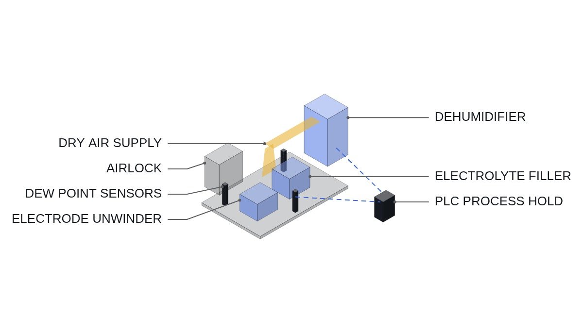
The conclusion first. The most common design error in a dry-room dew point interlock is wiring it as a single line: “dew point over limit → stop everything.” What must stop when dew point rises is the process exposed to moisture (electrolyte filling, electrode unwinding, transfer of open cells), not the dehumidifier and supply fans that remove that moisture. If the process-stop signal and the utility-run signal are not separated, the interlock actually delays recovery. This article lays out the monitoring signals, staged stops and return conditions against the I/O map.
Safety interlock conditions first
A dry room is an enclosed space that people enter, and it is also a space where electrolyte and flammable solvents are handled. Before designing the quality interlock, fix the conditions that concern people and fire.
- □ EMO is a hardwired safety circuit that removes power from process equipment. State at design stage, with the rationale recorded, whether EMO also cuts the dehumidifier and supply fans or is separated from them. The PLC reads EMO status as a monitoring input only.
- □ Electric locks on airlock doors must release to the open state on power loss or emergency (fail-safe unlock), and the inside emergency release is hardwired, not routed through the PLC.
- □ Gas and fire detection in the electrolyte handling area is owned by the fire system. The dry-room PLC responds to that signal only by stopping the process; ventilation changeover follows the fire system sequence.
- □ Where the layout calls for oxygen or CO2 monitoring (for example, a nitrogen-purged glovebox in the room), that alarm ranks above the dew point alarm.
Only once these four lines are fixed can the dew point interlock be designed independently as a quality interlock. A quality interlock that touches people’s egress path or the fire response is not acceptable.
Monitoring signals and decision logic
Dew point sensors respond slowly. Depending on sensor type and location, there is a lag between actual moisture ingress and the reading rising, so a single absolute value decides too late. Split the decision inputs three ways.
- Absolute value: three representative room dew point sensors voted 2oo3. The decision holds even with one sensor failed or under calibration.
- Rate of rise: if dew point rises faster than a setpoint over a defined time window, raise an early warning. This input prepares a process pause before the absolute limit is reached.
- Cause signals: room differential pressure (positive pressure held or not), both airlock doors open, dehumidifier regeneration heater and rotor status, supply air temperature. These change before dew point does.
The setpoints themselves (dew point limit, rate limit) are set by the cell chemistry and process specification, so they are kept as variables here (DP_HI_SP, DP_RATE_SP). Sensor-to-sensor offset and placement effects differ per installation and are corrected after field measurement.
Staged response comparison
| Stage | Trigger | Process action | Utilities |
|---|---|---|---|
| Early warning | Rate high or cause signal | Hold new lots | Keep running, check regen |
| Process hold | 2oo3 over limit | Stop fill and unwind, seal open cells | Keep running, limit airlock entry |
| Process stop | Limit persists or dehumidifier trip | All process to safe position | Start standby dehumidifier |
| Return | Below limit for stable period | Manual check, staged restart | Normal |
The point of the table is that the utilities column never turns to “stop.” The dew point interlock stops the process, and the dehumidification system should be running at maximum duty while the interlock is active. If the two signals are tied to the same output bit, the I/O map has to be split first.
PLC logic example
(* I/O MAP
   %I1.0  DI_EMO_LOOP_OK         : EMO hardwired loop healthy (monitor only)
   %I1.1  DI_FIRE_GAS_ALARM      : fire/gas signal from fire panel
   %I1.2  DI_DEHUM_RUN           : dehumidifier running feedback
   %I1.3  DI_DEHUM_TRIP          : dehumidifier trip (regen heater / rotor fault)
   %I1.4  DI_AIRLOCK_DOOR_A_OPEN : airlock outer door open
   %I1.5  DI_AIRLOCK_DOOR_B_OPEN : airlock inner door open
   %I1.6  DI_RESET_PB            : process hold manual reset push button
   %IW200 AI_DP_1                : dew point sensor 1, 0.1 degC/digit
   %IW202 AI_DP_2                : dew point sensor 2
   %IW204 AI_DP_3                : dew point sensor 3
   %IW206 AI_ROOM_DPRESS         : room differential pressure, 0.1 Pa/digit
   %Q1.0  DO_NEW_LOT_PERMIT      : new lot input permit
   %Q1.1  DO_FILL_UNWIND_PERMIT  : electrolyte fill / electrode unwind permit
   %Q1.2  DO_DEHUM_STBY_START    : standby dehumidifier start
   %Q1.3  DO_AIRLOCK_ENTRY_HOLD  : airlock entry hold lamp and lock request
*)
VAR
  DP_HI_1, DP_HI_2, DP_HI_3 : BOOL;
  DP_HI_2OO3   : BOOL;
  DP_RATE_HI   : BOOL;   (* computed by trend FB, window set by process spec *)
  CAUSE_ALARM  : BOOL;
  T_HI_PERSIST : TON;
  T_RECOVER    : TON;
  PROCESS_HOLD : BOOL;
END_VAR

DP_HI_1 := AI_DP_1 > DP_HI_SP;
DP_HI_2 := AI_DP_2 > DP_HI_SP;
DP_HI_3 := AI_DP_3 > DP_HI_SP;
DP_HI_2OO3 := (DP_HI_1 AND DP_HI_2) OR (DP_HI_2 AND DP_HI_3) OR (DP_HI_1 AND DP_HI_3);

(* cause signals change before dew point does *)
CAUSE_ALARM := (AI_ROOM_DPRESS < DPRESS_LO_SP)
               OR (DI_AIRLOCK_DOOR_A_OPEN AND DI_AIRLOCK_DOOR_B_OPEN)
               OR DI_DEHUM_TRIP;

(* stage 1: early warning holds new lots only *)
DO_NEW_LOT_PERMIT := DI_EMO_LOOP_OK AND NOT DI_FIRE_GAS_ALARM
                     AND NOT DP_RATE_HI AND NOT CAUSE_ALARM AND NOT PROCESS_HOLD;

(* stage 2: 2oo3 high latches process hold; release needs stable recovery time *)
T_RECOVER(IN := NOT DP_HI_2OO3 AND NOT DP_RATE_HI, PT := T#30M);  (* example value *)
IF DP_HI_2OO3 THEN PROCESS_HOLD := TRUE;
ELSIF T_RECOVER.Q AND DI_RESET_PB THEN PROCESS_HOLD := FALSE;     (* manual reset *)
END_IF;

DO_FILL_UNWIND_PERMIT := DI_EMO_LOOP_OK AND NOT DI_FIRE_GAS_ALARM AND NOT PROCESS_HOLD;

(* stage 3: persistent high or dehumidifier trip starts standby unit; utilities never stopped here *)
T_HI_PERSIST(IN := DP_HI_2OO3, PT := T#10M);                      (* example value *)
DO_DEHUM_STBY_START := T_HI_PERSIST.Q OR DI_DEHUM_TRIP OR NOT DI_DEHUM_RUN;
DO_AIRLOCK_ENTRY_HOLD := PROCESS_HOLD;   (* request only; egress release stays hardwired *)
The timer values in the code (30 min, 10 min) are examples. The recovery wait depends on room volume, dehumidifier process airflow and how fast moisture desorbs from surfaces that absorbed it, so record the actual recovery curve and set it from that. DO_AIRLOCK_ENTRY_HOLD only requests an entry restriction; it never blocks the way out of the room.
Field verification checklist
- □ Are the three dew point sensors spread across the supply diffuser zone, the airlock area and the process equipment area?
- □ Have the sensor calibration interval and the voting behavior during calibration (switch to 1oo2 with one sensor excluded) been tested?
- □ Is simultaneous opening of both airlock doors wired as a cause signal, and does the door interlock never block egress, even on PLC failure?
- □ Does the dehumidifier trip come in as a voltage-free contact, with a broken signal wire judged as a trip (normally closed wiring)?
- □ Is there a defined holding location (such as a sealed waiting chamber) for open cells and electrodes during a process hold?
- □ Is the restart order (unwind → stack → fill) documented, so that not every machine restarts at once?
Boundary conditions
There are conditions under which this separated design is wrong. First, if an alarm suggests the dehumidifier itself is the fire source (regeneration heater overheating), the fire sequence overrides the “utilities never stop” principle. Second, if the dry room is small and serves a single machine, staged response gains little and an immediate stop on limit exceedance is simpler to operate. Third, with only one sensor, the rate-of-rise decision can be pushed around by noise; tying the early warning to a process stop without waveform analysis and field measurement will increase false stops.
The single decision rule: if the dew point interlock output has any path that stops dehumidification or supply air equipment, remove every such path except the one owned by the fire sequence.