The substance of the monitoring mandate is not surveillance but securing a channel to execute remote output control (curtailment).
The conclusion first. The Ministry of Climate, Energy and Environment announced on September 3, 2026 that it has completed the revision of the regulations on the use of transmission and distribution facilities. The threshold for mandatory installation of renewable energy monitoring and control equipment is being expanded from facilities of 90kW or more to 20kW or more, taking effect next year (2027). The scope covers solar, wind and fuel cell generation facilities, and the aim is to secure grid stability in response to the expansion of renewables to 100GW by 2030. Generators with facilities of 20kW or more must settle on their communication network method and remote output control interface in the time remaining.
The fact that existing facilities are not covered retroactively, paradoxically, makes the new 20kW threshold weigh more heavily.
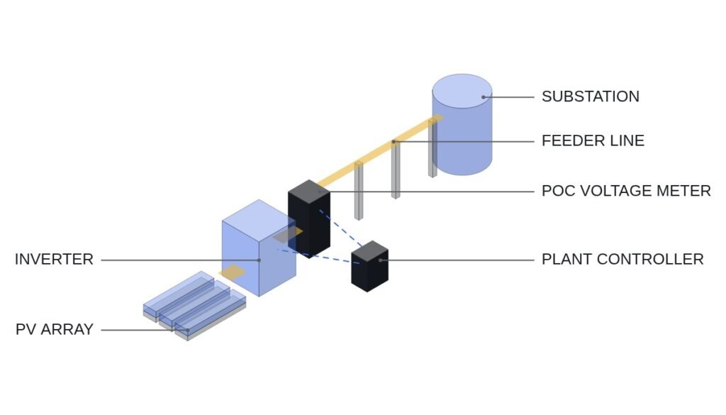
E2News reported on September 3, 2026 that the Ministry of Climate, Energy and Environment had completed a revision of the regulations on the use of transmission and distribution facilities, expanding the mandatory installation of renewable monitoring and control equipment from 90kW or more to 20kW or more. Monitoring and control equipment refers to facilities that check the output and operating status of solar and wind generators in real time, transmit them to the grid operator, and allow output to be controlled remotely when needed.
The mandate started in 2020 with facilities of 100kW or more on Jeju Island and has gradually widened in scope, while facilities built before the mandate have not yet been covered retroactively because of opposition from generators and the cost burden. Abroad, Germany has applied the same obligation to facilities of 25kW or more since 2021, and Kyushu Electric Power in Japan to facilities of 10kW or more since 2022.
To lower the installation cost burden, the government plans to allow the use of mobile carriers’ commercial LTE networks instead of KEPCO’s private network (e-WSN), in which case installation cost is expected to drop from about KRW 4.6 million to about KRW 2 million, and the activation period from an average of 84 days to about 10 days. Lee Jae-sik, Director General for Power Grid Policy at the Ministry of Climate, said the revision will serve as a foundation for securing power grid stability for the expansion of renewables.
Preconditions: the detailed specifications for the communication protocol and remote output control interface (RTU communication method, command update period, etc.) have not been published in the text of the revised regulation, so the checklist below is developed on the basis of a general configuration in which a renewable generation facility performs output monitoring and remote output control through a SCADA-based RTU. In actual application, it must be verified and replaced with the original text of the revised regulation distributed by KEPCO and the Korea Power Exchange and with the communication carrier’s specifications.
Safety interlock check sequence (top priority)
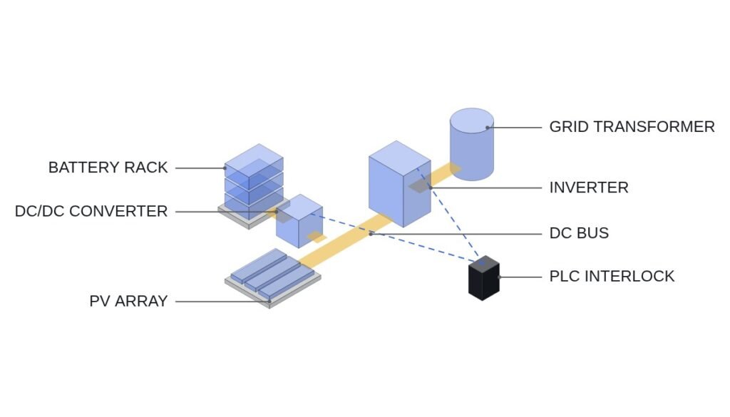
- Local protection relay priority interlock — the trip logic of the plant’s own overvoltage, undervoltage and overfrequency protection relays always takes precedence over remote output control commands. Remote output control is not designed to delay or replace the operation of local protection relays.
- Communication loss fail-safe interlock — when remote output control communication is lost for a set time (timeout), whether to hold the last command, return to rated output, or ramp down to the safe side must be confirmed in the detailed clauses of the regulation and in the grid operator’s guidelines.
- Command validity interlock — if a received output control command falls outside the facility’s rated range, it is limited by a soft limit, and an abnormal command is discarded while the previous valid value is held.
- Communication network redundancy interlock — if a commercial LTE network is used as the single path, check in advance that a line failure automatically switches to the communication loss fail-safe interlock.
- Anti-islanding protection — must be maintained through hardware protection relays interlocked with circuit breakers, independent of the interlock scheme above; designs that replace or bypass it with software logic alone are not covered on this site.
I/O map for renewable monitoring and control equipment
| Signal | I/O address | Type | Operating condition |
|---|---|---|---|
| Output measurement | AI301 | Analog In 4-20mA | Real-time output transmitted continuously, uploaded periodically to the grid operator’s server |
| Operating status | DI301 | Digital In | 1 = normal operation, 0 = stopped or faulted |
| Communication status (heartbeat) | DI302 | Digital In | Monitors the server response period; timeout is judged as communication loss |
| Remote output control command | AO301 | Analog Out | Grid operator setpoint (0–100%), soft upper and lower limits applied |
| Communication loss fail-safe | DO301 | Digital Out | 1 on DI302 timeout (enters predefined safe mode; detailed behavior to be confirmed) |
| Local protection relay trip | DO302 | Digital Out | Trips immediately on overvoltage, undervoltage or overfrequency regardless of remote command (top priority) |
The implication of this I/O map is clear. If AO301 (remote output control command) and DO302 (local protection relay trip) sit in the same priority logic, there is a risk that under communication delay the remote command slows down local protection. Generators with facilities of 20kW or more should first confirm, at the stage of selecting a communication network, that DO302 operates on a hardware path independent of AO301.
PLC logic snippet (IEC 61131-3 Structured Text pseudocode)
(* Renewable monitoring/control fail-safe logic - local protection takes priority *)
(* AI301: output, DI301: operating status, DI302: comm heartbeat, AO301: remote output control command *)
IF (GRID_VOLT_ABNORMAL OR GRID_FREQ_ABNORMAL) THEN
    DO302 := 1; (* Local protection relay trips immediately, remote command ignored *)
ELSIF DI302 = 0 THEN
    DO301 := 1; (* Enter comm-loss fail-safe, detailed behavior to be confirmed *)
ELSE
    AO301 := AO301_REMOTE_REF; (* Apply remote output control command while comm is healthy *)
    DO301 := 0;
END_IF;
(* DO302 is kept on an independent hardware path unrelated to AO301 and DO301 *)
Boundary conditions — responding to field variables
The exact fail-safe behavior on communication loss (hold command, return to rated output, or ramp down) and the update period of remote output control commands could not be confirmed from the detailed clauses of the revised regulation or the grid operator’s communication specifications, so they require waveform analysis and field measurement. Whether the government will further extend the scope below 20kW has also not been confirmed. The selection criterion comes down to one question: when reviewing how to build the communication network, is the local protection relay trip path physically separated from the remote output control communication path?
References
E2News, “Monitoring and control equipment mandatory for renewables of 20kW or more from next year” (2026-09-03)
KR101565895B1 — Korea University of Technology and Education Industry-Academic Cooperation Foundation (now SR Energy Co., Ltd.), Remote monitoring system for a photovoltaic power generation system and method thereof (Google Patents, status Active)