VOLTENERTEC WEEKLY · 2026 Week 38 · 4/5
To state the conclusion first: the headline efficiency figures for perovskite/silicon tandem cells should not be carried straight into power-plant design. The criterion is not the peak efficiency number, but the area at which that number was measured. The 6.1-percentage-point gap between a 1 cm²-class cell at 35.5% and a 1.7 m² module at 29.4% is the range a system designer will actually face, and that gap is not a materials problem — it is a large-area uniformity problem.
What Gets Lost as Area Grows
Professor Seok Sang-il of the UNIST Department of Energy Chemical Engineering summarized the technical progress and commercialization challenges of perovskite solar cells in a keynote at NEXT Solar Busan, held September 16 at BEXCO in Busan. The certified efficiencies presented, ordered by area, are as follows.
| Category | Area | Certified Efficiency |
|---|---|---|
| Perovskite single cell | 0.05 cm² (5 mm²) | 28.0% |
| Perovskite/silicon tandem cell | 1 cm² (100 mm²) | 35.5% |
| Tandem cell (large-area) | 261 cm² (26,100 mm²) | 34.3% |
| Tandem module | 0.17 m² | 31.4% |
| Tandem module | 1.7 m² | 29.4% |
| Perovskite-only module | 0.72 m² | 22.0% |
The table says one thing. As area grew roughly 17,000-fold, from 1 cm² to 1.7 m², efficiency fell 6.1 percentage points, from 35.5% to 29.4%. This drop is not a theoretical material limit; it arises because thin-film thickness, composition, and crystalline state are not uniform across the full area — Professor Seok explained that defects and electrical resistance increase as area grows. It is the same category of problem that took silicon single-crystal modules decades to manage down to a cell-to-module loss of only a few percentage points.
The Advantaged Position and the Disadvantaged Position
Under current conditions, solar has already become a mainstream power source. Last year’s global new installations reached 664 GW, up 12% year-over-year, cumulative installed capacity hit 3 TW, and the levelized cost of electricity (LCOE) fell to $44/MWh, 89% below the 2010 level. Renewable energy’s share of global generation reached 33.8%, overtaking coal (33.0%) for the first time. In other words, the competitor is no longer fossil generation — it is already-cheap silicon modules.
Applying tandem cells extracts more power from the same area. The advantaged position is anywhere the constraint on area is more expensive than the constraint on output: dense urban sites with high land-lease costs, rooftop installations with high structural-reinforcement costs, building-integrated PV (BIPV) with a physically fixed installation area, and vehicle or portable power applications. Conversely, in spacious, low-cost ground-mount sites, tandem remains disadvantageous until module unit price falls enough to offset the 6.1-percentage-point efficiency advantage over silicon.
The chain of reasoning is simple. The value of one percentage point of efficiency converts into “the opportunity cost of one square meter of area.” Where that opportunity cost is low, there is no reason to use tandem.
Four Barriers to Commercialization
Professor Seok identified four barriers. Translated into system-design terms:
- Long-term stability — exposure to moisture, oxygen, heat, and UV light, internal ion migration, crystal-structure change, and interfacial reactions between materials all reduce durability. Encapsulation design and junction-box sealing must be tighter than for silicon modules.
- Large modules — exactly the gap shown in the table above. Procurement should specify the certified efficiency of the actual module size, not the cell efficiency.
- Lead management — rather than eliminating lead outright, Professor Seok proposed preventing external leakage on panel breakage and building a recovery/recycling system spanning production to disposal. For plant operators, this means a new on-site handling procedure for damaged modules.
- Standardizing evaluation criteria — there is a gap between lab-scale, short-area, short-term stability testing and industrial verification of finished modules for heat, humidity, UV, hail, and electrical safety. A lifetime figure from a paper cannot be carried over as a product lifetime figure.
What the Large-Area Reality Looks Like Through Patents
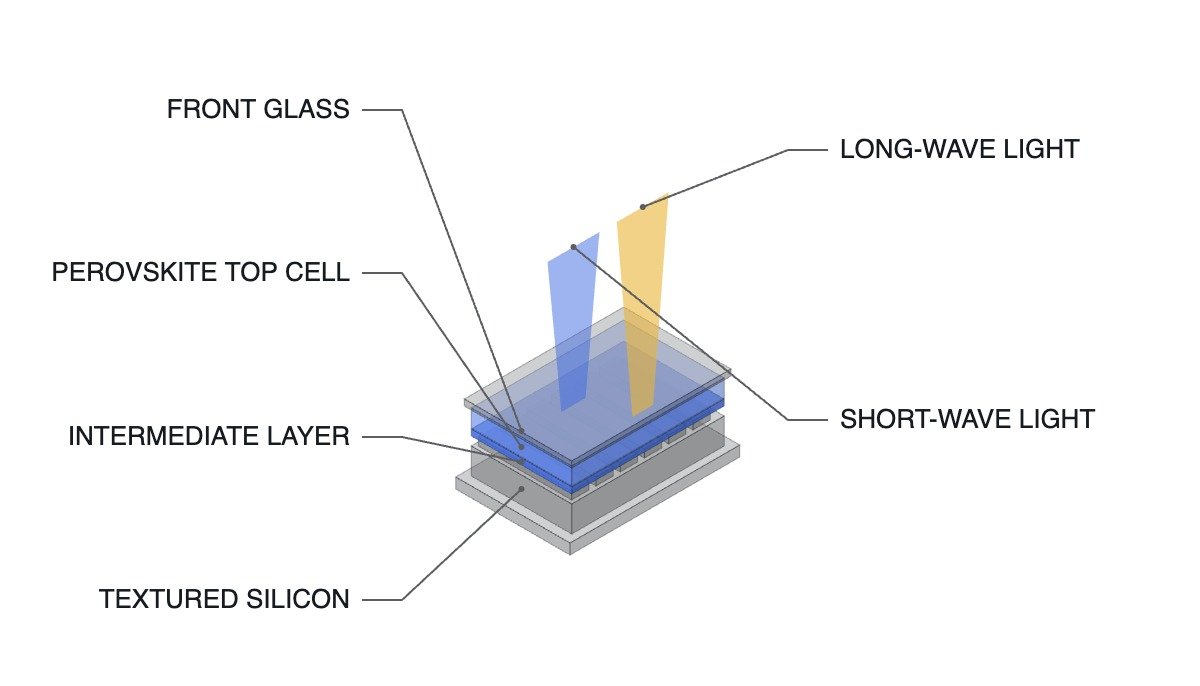
What makes large-area tandem difficult shows up directly in patent claims. US12317641B2, “Perovskite/silicon tandem photovoltaic device,” jointly assigned to the University of North Carolina at Chapel Hill and Arizona State University, describes placing a texture structure with a peak-to-valley height of less than 1 μm (0.001 mm) or less than 2 μm (0.002 mm) on the front (light-receiving) surface of the silicon cell, planarizing that textured surface with an intermediate layer, and then forming the perovskite layer on top. Filed 2020-08-12, granted 2025-05-27.
The claim content implies a practical point: a silicon cell is roughened on the surface to reduce reflection loss, but a uniform thin film on top of it requires flatness again. Lowering the texture height to the few-micron (thousandths-of-a-millimeter) range and filling it with an intermediate layer is the key process variable for large-area tandem, and this tolerance must be maintained across the full module area for the gap in the table to close.
Boundary Conditions — When Tandem Turns Disadvantageous
First, spacious ground-mount sites. Where the opportunity cost of area is low, the efficiency advantage is never recovered.
Second, degradation rate. Unless a degradation profile equivalent to silicon modules’ long-term warranty conditions is secured, the initial efficiency advantage can be offset by cumulative generation over the plant’s lifetime. Measured long-term degradation data for tandem modules has not been presented in currently available material, so this is left as an item requiring confirmation.
Third, system-design conditions. Because the top and bottom cells are stacked in series, string voltage and temperature characteristics can differ from a silicon-only module, so inverter MPPT voltage windows and string lengths cannot simply be carried over. Specific figures must be confirmed from the module manufacturer’s certified datasheet and are not asserted definitively here.
The single selection criterion is therefore set as follows: adopt tandem only where the opportunity cost per unit area is high, and only when the certified efficiency and long-term degradation warranty are given for the actual module specification — not the cell. A proposal that presents only cell efficiency is just the number in the upper-left of the table, not the number that reaches the plant.
Source: Electric Times article (in Korean), September 17, 2026