VOLTENERTEC WEEKLY · 2026 Week 38 · 5/5
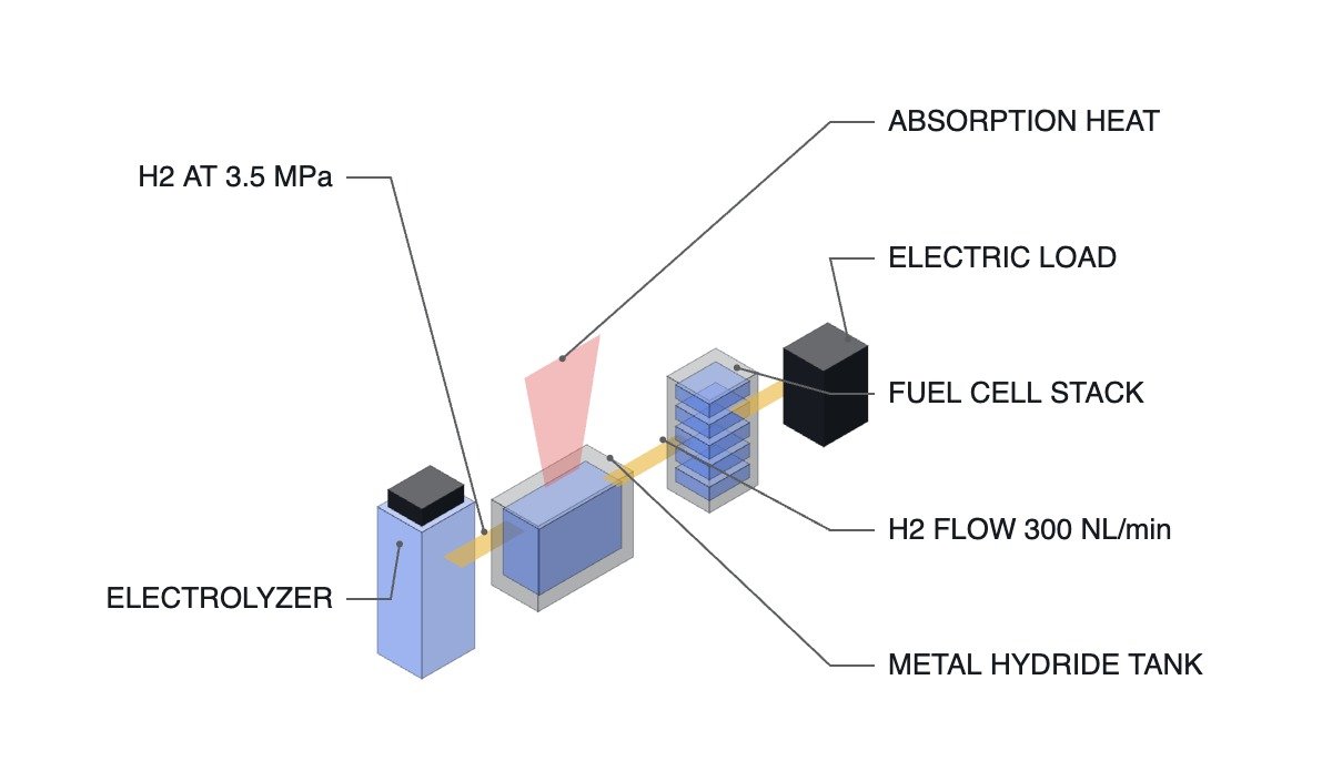
To state the conclusion first: solid-state hydrogen storage becomes advantageous over compressed hydrogen when the electrical power saved by cutting compression stages exceeds the equipment and time cost of managing absorption/desorption heat. The compressed-gas path spends compressor power climbing through 20 MPa, 35 MPa, and 70 MPa, while the solid-state path stops at 3.5 MPa — but it must handle the exothermic and endothermic heat of the metal hydride outside the electrical system. In short, it is a trade that moves an electrical problem into a thermal one.
Comparing the Pressure Paths
The 6th 2026 Ulsan International Hydrogen Energy Forum, hosted by the City of Ulsan and organized by the Korea Hydrogen Industry Association, was held September 10 at the Ulsan Exhibition & Convention Center (UECO). Professor Yongpan Cheng of North China Electric Power University presented on power systems based on solid-state hydrogen storage, comparing the supply paths of the two storage methods by pressure stage.
| Category | Pressure Path | Intermediate Equipment |
|---|---|---|
| Compressed hydrogen | 1.6 MPa → 20 MPa → 35/70 MPa → 0.1 MPa (point of use) | Compressor, transport truck, refueling station |
| Solid-state hydrogen | 3.5 MPa → 0.1 MPa (point of use) | Direct connection to electrolyzer, solid-state hydrogen charging unit |
The table says one thing. With solid-state hydrogen, it is not that the storage pressure is lower — the pressure stage itself disappears. The multi-stage compression that raises pressure from 1.6 MPa to 70 MPa consumes electrical power, and that power is deducted from the overall efficiency of hydrogen made from renewable energy. Fewer compression stages mean less load and less high-pressure piping to manage from an electrical-equipment standpoint. In exchange, something has to receive and supply the heat that the metal hydride releases and absorbs as it takes up and gives off hydrogen.
The Advantaged Position and the Disadvantaged Position
Under current conditions, storing surplus solar/wind power as hydrogen requires electrolysis followed by compression, transport, and refueling stages. Power and equipment are added at every stage, and a 70 MPa refueling infrastructure falls under high-pressure-gas equipment regulation. This fixed cost weighs more heavily the smaller the site.
Once solid-state storage is applied, hydrogen goes straight from the electrolyzer into storage at roughly 3.5 MPa and out to the 0.1 MPa point of use. The advantaged position is a site where storage volume is not large, charge/discharge speed is not urgent, and a place to reject and receive heat is nearby. The Chinese application cases Professor Cheng presented match this profile.
| Application Case | Scale |
|---|---|
| Patrol vessel | ~20 kW class |
| Port tractor vehicle | ~240 kW class, 19 kg hydrogen onboard |
| Solid-state hydrogen ESS | 65 Nm³ hydrogen, 300 NL/min discharge flow rate |
| Hydrogen-propulsion cruise ship | Length 29.8 m (29,800 mm), 130 kW output, 84 kg hydrogen |
| Two-wheelers / tourist vehicles | Low-pressure solid-state hydrogen storage vessels applied |
The number worth reading in this table is the 300 NL/min discharge flow rate — 300 L per minute at standard temperature and pressure, or roughly 18 Nm³ per hour, and the fuel-cell output band that can be matched to it is limited accordingly. The constraint on solid-state hydrogen is not storage capacity but discharge rate, and discharge rate is in turn tied to how fast heat can be delivered into the tank. This is exactly why it is disadvantaged in applications that require rapid load-following.
Equipment-Side Verification Order
When integrating a solid-state hydrogen storage system with electrical equipment, the verification order is as follows.
- Confirm that the hydrogen-leak detectors and ventilation system directly cut the power system through a hardwired path. The EMO (Emergency Off) and gas-detection circuit do not pass through control logic and are never replaced by software.
- Confirm the tank’s upper and lower temperature-limit interlocks. Absorption is exothermic and desorption is endothermic, so both directions must be monitored.
- Monitor the flow rate and temperature of the heat-transfer-medium circulation system. If heat cannot be removed, absorption stops; if heat cannot be supplied, desorption stops. This stoppage is normal behavior, not an equipment failure, so alarm classification must distinguish the two.
- Coordinate the discharge-flow lower limit with the fuel-cell output command. Limit output from a higher level so the stack’s output command never exceeds the tank’s discharge capability.
- Confirm the pressure upper limit. Even in the 3.5 MPa band, the upper limit must account for the rise in equilibrium pressure that comes with rising temperature.
The Thermal Problem, Seen Through Patents
That heat is the central variable in this approach also shows up in patents. US10581101B2, “Solid state hydrogen storage device,” assigned to Hyundai Motor Company, describes a device consisting of a first storage section holding a reversible solid-state hydrogen storage material, a reactor arranged within it that carries out a hydrolysis reaction of a non-reversible solid-state hydrogen storage material, and a fuel-cell stack, and states explicitly that the non-reversible storage material releases heat when hydrolysis is performed. Filed 2016-11-22, granted 2020-03-03; legal status is Active, with an adjusted expiration of 2037-11-25.
In other words, this patent is not solving “how to hold the hydrogen” but “where to source the heat needed for the reversible storage material to release its hydrogen” — through the device’s own configuration. That securing a heat source is not a secondary concern but a variable that determines the device configuration itself is visible directly in the claim structure.
Boundary Conditions — When Solid-State Hydrogen Turns Disadvantageous
First, weight. Metal hydrides carry a large vessel weight relative to the amount of hydrogen stored. This is likely why the cited cases skew toward weight-tolerant applications such as port tractors (19 kg hydrogen) and ships; the weight budget for scaling to passenger mobility is not given in the disclosed material — an item requiring confirmation.
Second, charge/discharge speed. As shown above, desorption is tied to heat-supply rate. In applications requiring fast charging or sharp load swings, this is disadvantageous relative to compressed hydrogen.
Third, scale. As storage volume grows, heat-exchange area and circulation power grow with it, so the power saved on compression is spent again on thermal-system equipment. The break-even scale depends on site conditions and is not asserted definitively here.
The single selection criterion is therefore set as follows: solid-state hydrogen is advantageous over compressed hydrogen only for small-to-mid-scale storage where the discharge-flow requirement is moderate and a waste-heat or low-temperature heat source is already available on site. Where a heat source must be built from scratch, the power saved by cutting compression stages ends up spent again in the thermal system.
Source: Electric Times article (in Korean), September 14, 2026