Bottom line first. Choosing between a fuel cell backup generator and a diesel standby generator is not about which is greener. It comes down to output (kW) multiplied by backup duration (h), and who carries the burden of routine test runs. At a few-kW telecom site where output is small and backup runs from a few hours to under a day, PEMFC backup wins by removing both light-load running problems and the routine testing burden. At a MW-scale data center that needs tens of hours of backup, hydrogen storage grows linearly and struggles to match the fuel energy density of diesel.
Where it wins, where it doesn’t
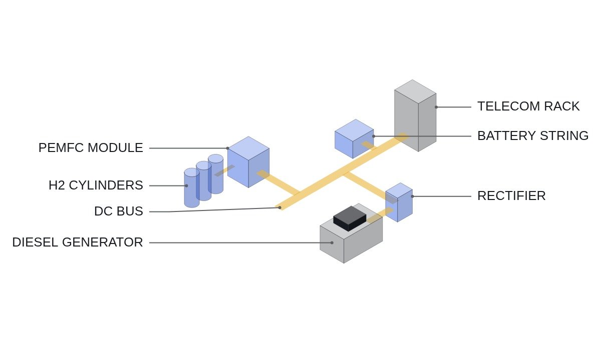
Start with the current state. Emergency power at telecom sites and data centers is mostly “UPS or DC battery + diesel generator”. The battery takes the instant of the outage, and once the generator has started and established voltage and frequency it picks up the load. Diesel became the default in this arrangement because backup time can be stretched simply by sizing the fuel tank.
Put diesel at a small base station and the problem that shows up is operating condition rather than output. When actual load is small relative to generator rating, the set runs lightly loaded for long periods, combustion is incomplete, and unburned fuel builds up in the exhaust, the so-called wet stacking. Add routine test runs, fuel degradation management and noise and exhaust complaints, and you end up sending maintenance crews around remote sites for a few kW of load.
PEMFC backup removes most of those operating-condition problems. A stack does not lose efficiency at light load; if anything, cell voltage rises. With no rotating machinery, test runs carry little mechanical burden. A new constraint appears instead. The mass of stored hydrogen is the backup time, and doubling backup time means doubling the hydrogen cylinders. The advantage of decoupled power and energy turns into a storage volume disadvantage at large scale.
The connecting logic: diesel is strong at “big and long” and weak at “small and frequently tested”. PEMFC is the opposite. Fix the kW and h of the application first and half the decision is made.
Converting backup energy to fuel quantity
Calculate two scales with assumed values. Common assumptions: hydrogen lower heating value 33.3 kWh/kg, fuel cell system efficiency 50%. Diesel lower heating value about 10 kWh/L, diesel generator efficiency 30% at light load and 35% at rated load for a large set.
Telecom site: 3 kW load and 72 hours of backup need 3 × 72 = 216 kWh. In hydrogen that is 216 ÷ (0.5 × 33.3) ≈ 13 kg; in diesel, 216 ÷ (0.3 × 10) = 72 L. Thirteen kilograms of hydrogen fits in a bundle of high-pressure cylinders on a base station plot, and at this scale storage volume is not the deciding constraint.
Data center: 2 MW load and 24 hours of backup need 48,000 kWh. In hydrogen that is 48,000 ÷ 16.65 ≈ 2,880 kg; in diesel, 48,000 ÷ 3.5 ≈ 13,700 L. The 13,700 L of diesel fits in one underground tank, but storing 2.9 tonnes of hydrogen as high-pressure gas on site turns the size of the storage plant and its separation distances into a site problem of its own. The formula is the same, but the moment the scale grows, the main variable of the comparison moves from efficiency to storage volume.
Comparison by application
| Application | Scale, backup time | PEMFC backup | Diesel generator |
|---|---|---|---|
| Telecom site (urban) | A few kW, hours | Wins. Silent, no exhaust | Loses. Light load, complaints |
| Telecom site (disaster) | A few kW, days | Neutral. Cylinder swap logistics | Neutral. Refuelling logistics |
| Edge data center | Hundreds of kW, hours | Conditional. Check site, separation | Wins. Proven configuration |
| Large data center | MW, 24 h or more | Loses. Storage volume too large | Wins. Fuel density |
| Strict emission zone | Any scale | Wins. No on-site emissions | Loses. Run hours may be capped |
The takeaway is that PEMFC backup’s advantage comes from load factor and installation environment rather than size. It is strong where the unit is small, tested often and hard to reach, and it struggles to replace diesel’s fuel storage structure where the plant is big and must hold on for a long time.
What the transfer architecture reveals
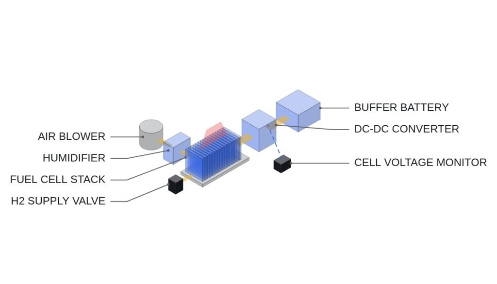
Neither option can carry the load at the instant of the outage. A diesel set needs time to start and build voltage, and NFPA 110 classifies emergency power levels by that time. A PEMFC also has to open the hydrogen supply valve, start the air blower and establish stack voltage, so the battery carries the load during start-up. Either way, battery capacity is sized on “how long until the generating source has finished starting”.
The difference is where it connects. Telecom sites mostly feed equipment from a −48 V DC bus, so a PEMFC can tie straight into that bus through a DC-DC converter with no AC transfer at all. Diesel output is AC and has to pass through a rectifier. A data center connects its generating source to the AC UPS input, so a PEMFC must also come out as AC through an inverter, and the DC-coupling advantage disappears.
| Item | PEMFC backup | Diesel generator |
|---|---|---|
| Output form | DC (via DC-DC) | AC |
| −48 V DC bus coupling | Direct | Via rectifier |
| Light-load operation | Little concern | Wet stacking risk |
| Extending backup time | Cylinders grow linearly | Tank expansion, relatively easy |
| Reference standards | IEC 62282-3-100, NEC 692, NFPA 2 | ISO 8528, NFPA 110 |
What to read from this table is that the DC-bus coupling advantage survives intact only at telecom sites. Move to an AC-UPS data center and the PEMFC picks up extra inverter losses, and its edge over diesel narrows to emissions and noise.
Items to check
- Fix the actual kW of the emergency load and the required backup time (h). Record design margin and actual load factor separately.
- Confirm the emergency power class and start-time requirement demanded by the authority having jurisdiction, including the NEC 700, 701 and 702 distinction.
- Size the battery on the source start-up time plus the retry time after a failed start.
- Place hydrogen storage with its separation distances, and the diesel tank with its spill containment, on the site drawing.
- Decide the routine test method (no load, real load, load bank) and remote monitoring points, and compare labour and fuel consumed per test.
Items to verify: fuel cell system efficiency and diesel part-load efficiency vary widely by product and load factor. The figures above are assumptions to show the method and should be replaced with the manufacturer’s fuel consumption curves by load.
Boundary conditions
PEMFC backup’s advantage flips under these conditions. First, when the backup time requirement grows. If disaster planning demands several days of backup, the cylinder count exceeds the site limit and cylinder swap logistics become harder than refuelling diesel. Second, when there is no local hydrogen supply chain. If the fill and return cycle for cylinders is long, the time to replace used cylinders itself becomes a backup gap. Third, large AC-centric facilities, where the DC-coupling advantage is gone and only the storage volume remains.
Diesel’s advantage, in turn, wavers where on-site emission and noise rules limit test run hours. A generator that cannot be test-run has no way to prove its reliability.
A single selection criterion to close. If the hydrogen quantity from load kW × backup h fits within the site’s separation distances and the supply bus is DC, choose PEMFC backup; if either fails, choose the diesel generator.